 Tweet
Tweet
The following pictures and directions should be used as a general guideline and in no way represents every year/modification. I will have a page of all the motor torque specs soon.
Parts
You will want to replace EVERYTHING when you replace the belt. It costs more now but it will save you time and more money later on.
You will want to replace EVERYTHING when you replace the belt. It costs more now but it will save you time and more money later on.
timing belt - 24502982
tensioner pulley - 24503561 bolt - 10162013
idler pullies - 24503859 bolt- 11514441
tensioner actuator - 24503860
Walkthrough
Start

Remove 2 10mm nuts for fuel rail cover

Remove Intake filter hose and PCV hose


Remove 2 8mm bolts for spark plug wire front cover. Also front valve cover vacuum line.

Unplug MAP sensor wiring and 2 plastic vacuum lines, 1 facing the front, one facing the rear. Pull metal vacuum line now if you can, otherwise it can wait till the plenum is unbolted.


Remove the throttle cables from the throttlebody.


Remove coolant overflow, 1 10 mm bolt and 1 10 mm nut


Remove front spark plug wires


Remove front spark plug wires

Remove front and rear timing belt inspection cover (2 8mm bolts)
Remove 7 10mm bolts holding plenum down.


Remove 7 10mm bolts holding plenum down.
Remove PCV valve to plenum and vacuum line beneath it.


Remove fuel line bracket to lower intake with 10mm open end wrench. Also use pliers and a screwdriver to remove Coolant line from beneath the throttle body.

Heater core hose bracket at TB. 10mm Bolt.


Heater core hose bracket at TB. 10mm Bolt.

Remove TB cables from the bracket using a screwdriver to pry them out the side.


Remove brake booster hose. Also remove the IAC and TPS wiring and remove plenum.

Remove vacuum line to oil distribution block
Remove valve covers (4) 8 mm bolts

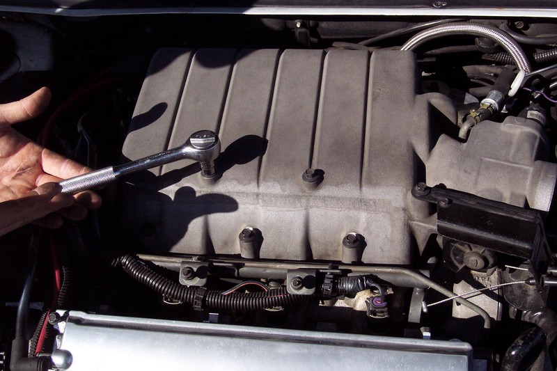
18mm wrench on tensioner to remove serpentine belt

Remove Cam Cover (9) 8mm bolts.
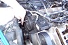
Remove power steering line from pump using 16mm wrench and screw driver. Leave them in place for now.

Remove (3) 13mm bolts holding PS pump in place
Put the lines into a plastic bag to collect fluid.

Remove (2) 10mm nuts holding plastic cover on passenger strut tower brace.
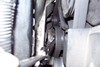
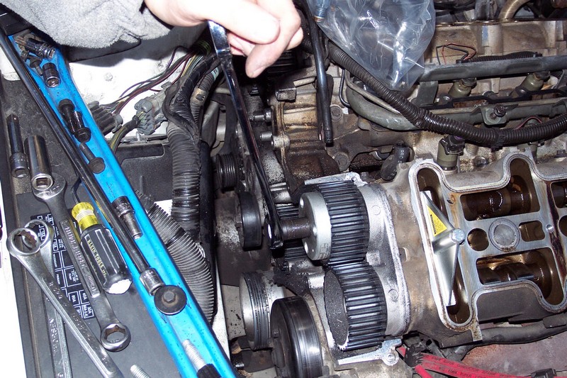
18mm wrench on tensioner again to push it down so that the timing belt cover can be removed.
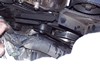
T-50 torx bit is used to remove the idler pullies and tensioner (actuator) pulley. Hold the serpentine belt tensioner down for the 3rd time after pullies are removed to get the old belt off the drive belt gear.

Remove (2) 13mm bolts holding belt tensioner in place.
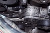
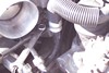
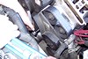
Retract the tensioner with a small screw driver. There should be a plastic plug on the end of the tensioner. Remove this and oil should come out (if not, you will be adding oil anyway). Screw the tensioner back in and then use a small paperclip though the rubber plug on the side. There is a small hole in it for a paperclip to fit in. You will have to back off the tensioner some to find the hole inside the plug so the paperclip goes all the way in. Picture is of the paperclip in place and the tensioner ready for reinstall.


First use a 15mm socket to rotate ALL cams with the flats face up. Then remove cam gear bolt using cam gear holding tool and 15mm socket. The rear cam gear will NOT come off without pulling the cam carrier on a 91-93 engine due to the lock ring setup. 94+ can remove all 4 cam gears easily.
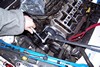
Install cam flat tools on front bank. Before installing the flat on the rear bank, you must decide what timing you want the rear exhaust cam to be (91-93 only, 94+ can install both cam flats now)
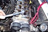
Pull cam gears off using cam gear puller (91-93 only) to remove lock ring. Reinstall gears without lock ring and put bolt back in but not tight. Leave about 1/4" space between washer and gear.

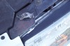
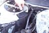
Rotate crank to desired rear bank timing using 15mm socket and wrench. 2nd picture shows the timing mark on the dampener.

Engine torn down the most. Reinstall starts here

Clean up any black hairs from the previous belt. Put belt in place. Push serpentine belt tensioner down again to put belt on the drive gear.

There are a few different ways to get both idler pullies back in and the tensioner with pulley. I prefer to put the tensioner in first (2) 13mm bolts and then the T50 for the pulley. Make sure the nub on the tensioner lines up with the socket part on the pulley. Also make sure the paperclip stays in place for now. After those are in, it is time to put the 2 idler pullies in place.


Remove vacuum line to oil distribution block

Remove valve covers (4) 8 mm bolts

18mm wrench on tensioner to remove serpentine belt


Remove Cam Cover (9) 8mm bolts.

Remove power steering line from pump using 16mm wrench and screw driver. Leave them in place for now.

Remove (3) 13mm bolts holding PS pump in place

Put the lines into a plastic bag to collect fluid.

Remove (2) 10mm nuts holding plastic cover on passenger strut tower brace.

18mm wrench on tensioner again to push it down so that the timing belt cover can be removed.

T-50 torx bit is used to remove the idler pullies and tensioner (actuator) pulley. Hold the serpentine belt tensioner down for the 3rd time after pullies are removed to get the old belt off the drive belt gear.

Remove (2) 13mm bolts holding belt tensioner in place.

Retract the tensioner with a small screw driver. There should be a plastic plug on the end of the tensioner. Remove this and oil should come out (if not, you will be adding oil anyway). Screw the tensioner back in and then use a small paperclip though the rubber plug on the side. There is a small hole in it for a paperclip to fit in. You will have to back off the tensioner some to find the hole inside the plug so the paperclip goes all the way in. Picture is of the paperclip in place and the tensioner ready for reinstall.


First use a 15mm socket to rotate ALL cams with the flats face up. Then remove cam gear bolt using cam gear holding tool and 15mm socket. The rear cam gear will NOT come off without pulling the cam carrier on a 91-93 engine due to the lock ring setup. 94+ can remove all 4 cam gears easily.

Install cam flat tools on front bank. Before installing the flat on the rear bank, you must decide what timing you want the rear exhaust cam to be (91-93 only, 94+ can install both cam flats now)

Pull cam gears off using cam gear puller (91-93 only) to remove lock ring. Reinstall gears without lock ring and put bolt back in but not tight. Leave about 1/4" space between washer and gear.
Rotate crank to desired rear bank timing using 15mm socket and wrench. 2nd picture shows the timing mark on the dampener.


Engine torn down the most. Reinstall starts here

Clean up any black hairs from the previous belt. Put belt in place. Push serpentine belt tensioner down again to put belt on the drive gear.


There are a few different ways to get both idler pullies back in and the tensioner with pulley. I prefer to put the tensioner in first (2) 13mm bolts and then the T50 for the pulley. Make sure the nub on the tensioner lines up with the socket part on the pulley. Also make sure the paperclip stays in place for now. After those are in, it is time to put the 2 idler pullies in place.

Put the top idler pulley in after the lower one. Do not install either bolt for the idlers until BOTH are in place. You will need to manipulate the belt some to get them in place due to the lip on the backside of the pulley.

Now put the bolts in hand tight, and then torque them down.

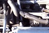
New belt in place.

Pull the paperclip from the tensioner.

Apply 12-20 pounds of pressure on the belt using a 3/8 extension and 11mm wrech


Stock timing setup
Install the lockring on the rear intake cam.
Pull the rear hold down tool.

Rotate the crank 360 degrees so that the rear cam flats are now face down. The crank mark should line up with the arrow on the timing chain cover. Install lock rings on the front cams and remove the front hold down tool. Now both banks are timed and its reinstall from here.
Altered timing, using 13* exhaust retard as example
Pull the rear hold down tool.
Using a dial indicator or any other method to accurately measure/mark a depth, measure from the cam flat to the bolt head holding the cam carrier to the head. It is either this method or make a cam flat tool that will hold only 1 cam at a time. When you rotate the crank over 360 degrees, the cam might still move some. You will need to hold down the intake cam still or measure it since only the exhaust will be locked down during the intake cam timing
Rotate the crank 360 degrees to do the front exhaust cam. Install the lock ring and then pull the cam flat tool.
Rotate the crank 347 degrees (watch the timing mark) and verify the rear intake cam is flat. Install lock ring and hold the cam gear in place with the cam gear holder. Repeat for the front intake cam.
Now both banks are timed and its reinstall from here.