Announcement

Collapse
No announcement yet.

Project "independence day"IRS and 3500 swap

Collapse
X
 
  • Filter
  • Time
  • Show
Clear All
new posts

  • Driver_10
    replied
    I got a bit more work done on strengthening the brackets. I couldnt find a aluminum of satisfactory thickness in since all of the metal supply shops were closed monday. I bought some 110 wall aluminum tubing and used it to make the reinforcement for the brackets.

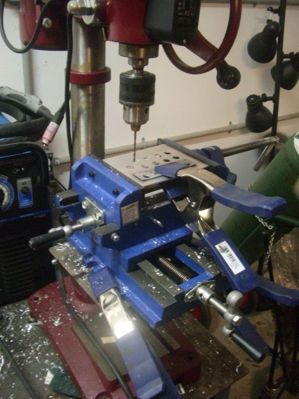
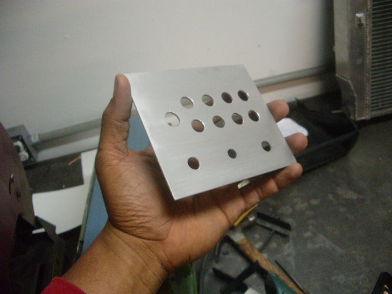
    I didnt come out as pretty as I would have liked, but its finctional.


    I even added a boss for the pulley. Replacing a worn pulley will be a snap


    It mounts well and feels good and sturdy. I also got the DS pump bracket finished.


    I first tried making it out of aluminum, But I didn't like the feel of it. So I went ahead and made a sturdier on out of steel. It should be plenty sturdy!


    Starting to look more like a proper race engine

    Leave a comment:


  • pocket-rocket
    replied
    Wow, man. The progress and quality of it looks good I envy your shop too.

    Sent from my HTC One X using Tapatalk 2

    Leave a comment:


  • Driver_10
    replied
    I had put the project down for a long time after it got flooded in Ike a couple of years ago. Now that Ive got a shop and some decent equipment, I can move on with completing it. Who knows, maybe I wont grenade the engine this time like I did the 3400.

    Leave a comment:


  • MidnightriderZ24
    replied
    happy to see this moving along! car looks great, amazing work man.

    Leave a comment:


  • Driver_10
    replied
    I went ahead and added an extra pulley to direct more belt coverage for the AC pump and PS pump. This car will be belt-squeak free!

    Leave a comment:


  • Driver_10
    replied
    I managed to get the belt routing completed. The crank pulley has good belt contact and the pulleys are well located now. The bracket for the DRY-sump oil pump is moving along well too.on the lower left side. All of this, and Ill have plenty of room for a set of Equal Length, front facing headers. The DP will run comfortably over the K-member too.


    To make enough room for the PS pump, I had to cut the EGR mounting flange out of the way. It also cleared up room for the TPS harness. Also managed to give the AC pump a wide enough birth to clear the valve-cover.


    I also cut this happy little notch for the throttle body.


    Ill be spending the rest of the day making reinforcement for the brackets and may have a bit of time left over to work on the IRS swap.

    Leave a comment:


  • Driver_10
    replied
    I did a little more work tonight... Gonna need some trimming before the ALT bracket fits without interference.
    Might de-ugly the thing while Im at it.

    Yuck...


    EDIT:Now De-uglied... Gonna trim the AC/PS bracket back a little too.

    Leave a comment:


  • Driver_10
    replied
    I (as shown before} have been using the method of "plexiglass shaping" to make templates for the acc brackets. The of engineering the acc brackets has not been an easy one. In the midst of trying to find a usable design, I went through about $50 worth of plexi-glass.


    The job of cutting the 1/2 inch material was slow and arduous, so I took a gamble and used some 3/8 thick lexan sheets. They were a lot more cost effective and were easier to cut. The original bracket called for the AC pump to be on the Pass side of the car. However, due to the space constraints from the steering linkage the oil-pump had to take up residency on the pass side, leaving the driver side space for the AC pump.

    I had planned to run the headers up high over the accessories at first. the ALT and AC pump are stacked low here.


    I dropped that idea in favor of higher placed brakets that would allow the headers to run low making access to the spark-pugs easier and pipe routing more simplified.


    With the basic placement of the accessories now laid out now, I had the to find the space up high to run the ac bracets without the belt routing interfering with the space for the headers, BUT not being so high that it would make contact with the hood. The throttlebody was also an obstacle. I also quickly noticed that the belt routing was now in the way. This was easily remedied by the use of a bracket flange on the front of the water-pump to install an idler pulley (noticeable in the lower right side of the pic above)

    After repeatedly editing the templates, I finally found a good final arrangement and cut the first aluminum plate.


    After a brief test mounting, I found that the EGR flange was making slight contact with the reservoir snout. Ill go ahead and cut this off and weld it shut tommorrow.


    Tomorrow, Ill have the ALT bracket cut and Ill hopefully have finish the supporting structures to make everything nice and stout.

    Leave a comment:


  • Driver_10
    replied
    My roomie finally stop procrastinating and got his turbo payed off. The thing is a monster! A CT43 72mm "billet wheel" compressor with a water/oil-cooled, "triple ball-bearing" center cartridge and a t4 divided 1.15 AR exhaust housing. It will pump o touch over 120lbs of air. Thats about 1200hp worth of air! Were looking at making 900hp or so. (my 700hp CT36 is the smaller of the two)


    It rained today on and off, so I will more than like be removing the engine tomorrow to bail out the water and dry out the block, Despite this set-back, I also got a bit more work done on placing the accessory brackets.


    These templates are not quite ready to be duplicated in aluminum plate, but hopefully tomorrow, weather permitting, I will try to have at least one of them cut.

    Leave a comment:


  • Driver_10
    replied
    I decided to try moving the engine backwards and downwards in the engine bay one more time. The engine now sits an additional inch backwards and 3/4 of an inch downward in the bay. I'm not sure how much lower and closer to the center it sits compared to stock, but I can say that its quite a bit.

    Heres how it was before.


    Heres now


    The oil-housing now clears the mounting bracket.

    Also, here's the top clearance before


    and heres after


    The back of the firewall had to "messaged" with a hammer to fetch the extra clearance for the drivers-side cylinder head.


    I should have the mounts made this weekend assuming money permits
    (Ive got some crazy high electrical bills rights now:no

    Leave a comment:


  • Driver_10
    replied
    Roy's third gen was also fitted with my old steer-column since I never could get it to extend without making it feel wobbly. I went ahead and spend the $773 (ouch) and special ordered this woodward column and momo steering wheel through "Blainefabrications" for my car. Alan (a fabrication genius in his own right) welded up a special bulk-head plate and an undercowl braket for a "plug-n-play" install.


    I had also assembled and purchased some trailing arms at "Smilye's" performance shop to replace the "rubber-bushed" stock pair. I also special ordered a set of adjustable, "3-position", brackets that were CAD designed to accomodate the center of gravity of the car for optimal handling. The positions could be changed for drag-racing, road-course or wet-weather driving.

    (I will be setting myself about the task of getting these installed this week-end... hopefully)


    I now set myself about the task of installing the engine and trans in the car. My first job was to measure, cut, level and re-weld the pan to modify it for dry-sump oiling.


    After an agrivating struggle with liquid proofing the difficult to weld "cast aluminum", The pan was fitted to the engine and the engine and trans was test mounted into the bay.


    The top-end was mounted and the clearances noted. The 3500 top-end just barely clears the underside of the cowl, so Ill drop it about 1/2 inch to give it better top-clearance. Ill either cut or "message" the firewall out a bit to seat the engine back another inch or so. Otherwise, it looks

    Leave a comment:


  • Driver_10
    replied
    The next weekend. I tackled the approach differently and built a cradle to support the bat-wing in ride-height compression for better accuracy.


    Eventually... after a lot of patience and some "make-shift" alignments using the distance between the wheel-well, body line and door corner, I GOT IT RIGHT!


    With the rear sitting in a comfortable position, its was temporarily tacked into place and now awaits DS angle alignment with the tranny.

    I now placed my efforts on getting more materials for the swap and ordering more /building bits for the engine, turbo and lubrication system. (BTW... Im doing a separate thread for the 3500 engine!)


    Here's the beginnings of the surge-tank fuel system and fuel cell.


    Leave a comment:


  • Driver_10
    replied
    my first attemps at installing the minitub on the pass side were a bit clumsy but well anchored. The experience gave me a better scope of F-body structural anatomy and I learned quickly how much easier this job was when using a round "cut-off" wheel as opposed to a sawz-all and a plasma tourch. (although the torch was better for cutting the tops of the wells out)


    After partially installing the minitubs on the remaining driver's side (a real PITA btw), my technique had improved and the work was a lot cleaner. I felt as ready as I would ever be to start the IRS install so the first daring cuts were made and the metal began to burn. (BTW... it was around this time that some you started to notice the vague comments randomly popping up in threads here and there)


    After doing the first big bits of slicing, I tried lifting the IRS into position to get a scope of what was needed.


    After the first relatively easy task of cutting the wheel-wells out of the way for fabricating the cradle, the daunting task of actual placing the rear-end correctly was upon me. I started taking random measurements at different points in the car to find a common point of reference for placement. I finally decided to use the spot at the top of the spring perch as a common reference since it at least seemed to be level with the opposite side. I made my first lines and began cutting. This was followed by constructing the mounts for the bat-wing.


    (BTW... I learned very quickly why it isnt wise to run a cutting torch while wearing street-shoes)


    Im using a set of magnesium corvette 18 x 9.5 front and rear for this car. They fill the wheel wells rather nicely! They will be crucial when it comes time to mount the "6-piston" calipers and 13 z51 rotors!


    As glorious as this looked, I soon realized to my horror that the mounting point was entirely too high in the car and the suspension travel was severely limited. So I disgusting cut out the "pretty" brackets that I made and called it a day.

    The precise words that I used were, "fuck this shit, Im gonna eat some water mellon."


    continued...

    Leave a comment:


  • Driver_10
    replied
    I had some small things out of the way with my own 95' and was now ready for the big ugly stuff. It was also around this time that we started collecting parts for the old IROC Camaro project car ,dubbed "Project Lazarus".

    The expensive bits (engine, trans, Suspension, yata-yata) and other pieces were tracked down first. Ebay and LS1 tech to the rescue! We found a TICK stgII t56 for about $1,200. It was shipped with a flywheel, clutch/accel/brake pedal set and stock LS6 Clutch.


    Also got this LS6 aluminum block with a single cracked liner. Easily repairable by a competent machine-shop. Got it for $50! No kidding.


    Got this nice GEN I cast ls intake w/ 250hp shot, "on-port" wet nitrous injection.


    Soon afterwards, got this Callies "stock-stroke" forged crank and fluidine under-drive balancer.


    Also got KYB s/a dampers with a "coil-over" conversion and BMR tubular lower control-arms. Also Pre-purchsed the first set of "LS swap" road-race K-members for the car as well. However, they still haven't shipped yet since the piece is still in the prototyping stages. Ill post up pics of that later.

    It was around this time that the Wolfe Racing "Mini-tubs" arrived. And I started slicing into the two cars. I was still short of a few materials, so I tried my had at installing the wheel wells in the third-gen first.


    Leave a comment:


  • Driver_10
    replied
    The AC controller panel was cheap and flimsy looking so I decided that I would build an acceptable panel. With space in the dash being at a premium, I decide to go ahead and incorporate the controls on my toggle panel. So after buying a new dril-press and machining plane I went ahead redesigned the panel. (I even made a proper place for the meth controller)


    Heres the last test fitting of the revamped console before completely striping out everything from the car. It should work pretty good.

    Leave a comment:

Working...
X