
-
I will have to read this thread for more details on what your trying to get the circuit to do, but thay circuit is very easy to make, I'm pretty sure radioshack stocks 555 ics, but I'm not sure. PM me if you need electronics help. -
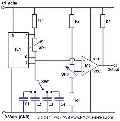
I waded through the blog where "MARKS" goes by the name "R NARKS" and culled out another circuitry diagram that was apparently th nexus of his CONTROLLER-DRIVER BOARD idea for his EFI Cleaner Machine. Once again... all of these electronic elements are Greek to me... but perhaps the more astute among us can take up this portion and run with it... Like Rick is doing, also... Here is the link to the project:
Leave a comment:
-
Okay Folks... (Looks like somebody broke us past 10,000 + hits on this topic!)
Hold on to your Hats... and your Short and Curlies...
Here is another engineering-style free thinker (...calls himself "marks" on YouTube) who has not only built his own fully functioning Fuel Injection Cleaning Machine and solved ALL the problems that prompted my initial thread question... but his device also makes "The FrankInjector Machine" look like Baby Shit! LOL.... I wish to Hell I could dope out what sort of mechanism he employs for his VFiFC component (Variable Fuel Injector Firing Component)...that thing works GREAT!!!!
Take a look at these YouTube Videos and you'll see what I mean!
I quote here what he has listed in the comments section on YouTube about this EFI controller...
"The links are on the "ford escort injector cleaner" video there are link to a blog page that shows where I got the idea for the rpm circuit, The 555 just gives a saw tooth output wave and the comparator gives the p/w modulation control. Also for the comment on the bottom I use 12 volts for the injectors and 5 volts for control, See referred links above."
Here is the link to the blog that has the actual nested link to the "How To Build" the thing that is what I have been waiting for now for so long...

Okay... Hopefully...after seeing some of these circuitry images at this link, some of our own folks who know and understand these things can figure out exactly what he used to make the controller and explain the parts and pieces of it... and then... show the rest of us how to build our own version... Yes?.....
MY GOD...THE MAN HAS EVEN GOT A HAND-DRAWN SCHEMATIC FOR HIS CONTROLLER-DRIVER BOARD THERE!
(Rick... I hope this does not dissuade you from making your own version with your "RIXinjector Machine)
Considering that "marks" conceived and built his own machine several years ago... (and deserves "High Marks" for it, too)...here is my observation concerning the originality of my own thinking...Originally posted by Superdave View Post
"There is NOTHING New Under the Sun..." William Shakespeare - Sonnet 59Attached FilesLast edited by 60dgrzbelow0; 07-14-2010, 07:19 AM.Leave a comment:
-
-
Robert... when Rick mentioned "DUNE" and you suggested using "SOUND TO CONTROL"... I just could not help but think of using THIS device.... Now THAT thing will modulate your EFIs to DEATH!Originally posted by robertisaar View Post
Attached FilesLeave a comment:
-
-
no, just thought it might be an easy way for those of us not so skilled with software, but are capable with hardware...Leave a comment:
-
It could be done without too much effort, but it doesn't make much sense (to me, anyway) to do it that way unless you had no other choice. The injectors should be fired with fast digital signals, but audio is analog, so you'd need to have a clipper or trigger to convert the analog to digital. The reliability of the coupling would depend on the amplitude of the sound source. It seems kludgy to me. Is it just that you're worried about the user interface being awkward or confusing?Originally posted by robertisaar View PostLeave a comment:
-
Well, a signal is a signal is a signal, ain't it? I mean from a controller input standpoint, of course. As to the corroded injector pins, I don't recall seeing that many on GM's, mostly on Nissans and Volvos.Leave a comment:
-
had an interesting idea...
how easy would it be to integrate a standard audio port into a device? thinking being that maybe it could be incredibly easy to literally plug a computer in, play a "sound" file in something(hell, maybe even repeat it) and have it trigger the injectors according to wether or not there is any sound... running them in specific duty cycles would be easy, i like messing with Audacity and creating tone patterns, makes setting up equalizers much easier... just wondering how much effort it would be for something like this.Leave a comment:
-
I'm curious, too. A little bit less planning and designing went into this than you might imagine. I measured the ID of the holes of some rails I have, then hit the hardware store to see what was available to work with. Then it's back home to arrange the bits and pieces and do the best with what I've got. It's an iterative processes as you can see in the photos from my first attempt. Kind of reminds me of playing with Legos and Construx...Originally posted by 60dgrzbelow0 View Post
Obviously I need to build a stand and find a better way of clamping the rail down than zip ties. Actually, some zip ties have release levers so they are reusable and that might be an option for the truly lazy... I've got a different idea, though. I found some electrical grounding clamps that look like this: The ground wire screw is 1/4-20. I'm thinking about drilling two holes at opposite ends of the base plate, clamping the grounding clamps on the fuel rail above, and screwing a threaded rod into the clamp. The base plate can then be held in place with two wing nuts. I'm just hoping that the wing nuts will have a low enough profile not to interfere with the spray pattern.
To suspend the whole thing over the graduated cylinders, I'm imagining a wooden A frame at either end of the fuel rail with pipe hangers attached at the apex. The hangers I have will fit over the end caps of the pipe and have a screw clamp, so I'll be able to rotate the assembly into position and then lock it down.
"RiXInjector Rail" Thanks for protecting my anonymity
it would be nice to see your present and future build images via a sort of permanent link to your photobucket posted at either the top and/or bottom of your threads. You mean in my signature? I did bury a link in my post somewhere, but I can see how it would be hard for anyone to notice once this thread goes to another page.
Granted! Do whatever you want with those photos. Go easy on the credits. Just a link back to the forum post or something is enough for meI would like your permission to "leech" some of your images to my own photobucket
Now you didn't really think I didn't catch that reference, did you?Oh..the only reason I call my machine "The FrankInjector" is in honor of James Whales' 1931 movie "Frankenstein"... We used to have a server in the office cobbled together from scrap parts that we referred to as "Frankenstein." I've also seen Tron while it was still fairly fresh and I'm no stranger to the saga of Dune

Leave a comment:
-
Rick... All I can say is...WOW!
At last... Everyone will be able to see what is possible from the imagination and hands of a Real Design Engineer! What you have made is so much more elegant and build-able, too. I'm certain everyone is as curious as I am to see how you set up the arrangement of your graduated cylinders for the Flow Matching portions of your test(s). If you design and create everything else as clean and compact as your "RiXInjector Rail"...I think it might induce more folks to try and build their own versions using design plans that will be much easier than mine to make and use. I am thrilled with your participation and I know that yours will make for a better success. If you can...it would be nice to see your present and future build images via a sort of permanent link to your photobucket posted at either the top and/or bottom of your threads. I would like your permission to "leech" some of your images to my own photobucket that will serve to give you credit and lead those other viewers back to the forum and read more on how you are doing things. Just let me know if that is Okay... Oh..the only reason I call my machine "The FrankInjector" is in honor of James Whales' 1931 movie "Frankenstein"...
Leave a comment:
-
Hmmm. I've never had injectors with corroded spades. I've never even noticed if they were plated or not, actually. Mine look like they might be plated or they might just be a bare alloy. I didn't spend much time looking. At 12V, you don't have to worry about shorting when submerged unless you're dunking them in salt water. I'm guessing the conductivity of purple power is pretty low. You did make me wonder if they are coated and if so, would the ultrasonic action degrade the coating. It knocked some paint off my injectors, but the electrical contacts still work and look fine. Your idea about re-plating the terminals is not a bad one, but I doubt if it would be worth the cost, effort, and toxicity/cleanup. I would just use Caig's Deoxit + power booster to clean up the corrosion and leave a protective coating. If I came across a harness with bad seals, I'd probably clean up the contacts and just squirt a little dielectric grease in there to prevent further corrosion.
Thanks for the tips about injector care. Thankfully I'm testing with a couple sets of injectors that have almost no value to me. I have some dime a dozen 19lb injectors and a set of 36lbers that have issues. I also have some 30lb guys I actually want to clean and use, and then there are the 3 or 4 sets of TBI injectors...
But I won't be dry-firing for long... My busy schedule has been rearranged a little and so I took some time the last couple of days to work on my own Frankinjector... Behold my uh... "Rickinjector Rail!" Yeah.
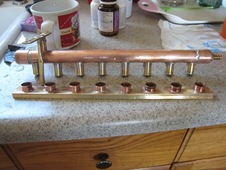
Any resemblance this bears to your copper pipe manifold is purely coincidence. I didn't even see your design until after I had put this together. Let me tell you the one critical difference, though: I'm using 0.014 wall thickness 9/16" OD brass tubing to compress the O rings instead of 1/2" OD copper pipe. If you do the math, the ID for the brass tubing comes out to 0.5345". I can tell you from direct comparison that this tubing is much tighter than copper pipe. According to my research, copper pipe comes in K, L, and M grades. The inner diameter of 1/2" K is 0.527", 1/2" L (most common in my stores) is 0.545, and 1/2" m is 0.569. If one could find the thick walled K copper pipe, it might work even better than the brass tubing. But I think the brass tubing will work fine.
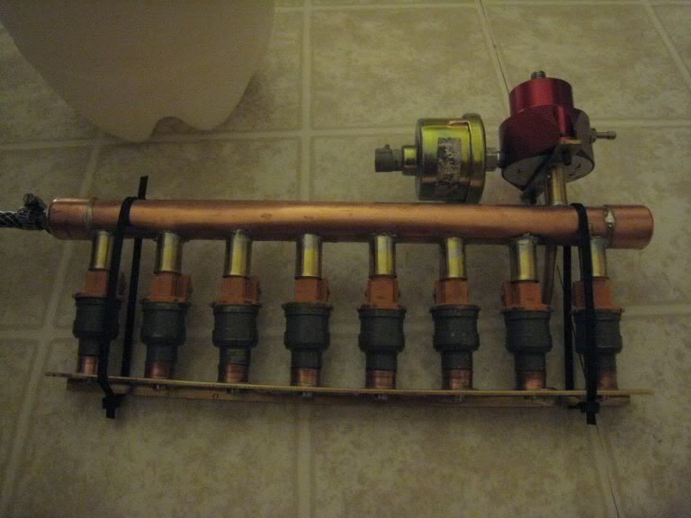
Many more pics Here
I made two attempts, the first using 5/8" brass tubing for the main rail and a standard piece of stamped steel for the bottom retainer. This was OK but I ruined the thin walled 5/8" tube when doing some drilling. That's when I decided to keep the 9/16" pipes and put them into a larger and sturdier 3/4" copper pipe. This worked out great. There's one trick I didn't take a picture of that anyone should know if they want to try to recreate this. To keep the brass tubes square and in alignment with each other, I places a 1/2" square stick of poplar in the copper tube and let the brass tubes rest on one of the flats of the stick.
I silver soldered everything with a propane torch. That was a new experience. The silver solder is very strong. It worked out well. My technique sucked until the very end of the project, though. Drilling 9/16" holes in the copper tubing was also a pain. Everything up to 3/8" or so was no problem, but 1/2" and 9/16" tended to tear up the pipe. I'm sure that using the right $40 bit would have made that a cakewalk, but I'm cheap. I found that going slow on the drill press up until it was just about to punch through, and then quickly jamming the press down made acceptable holes.
The bottom piece is something a little bit different. I drilled 3/8" holes which are a perfect fit for pintle caps but also work when the caps are removed. Then I made little rings out of 1/2" copper and placed them around the holes. These rings or cups are to allow the injectors to be flipped upside-down for backflushing. The O rings don't need to seat or seal in them. They just keep the injector pointed over the hole. I soldered a 1/4" brass strip on edge underneath the bottom brass plate to stiffen it and prevent flex under load. It's very rigid.
The final note is that I flared the ends of the 9/16" tubes and copper rings to make it easy for the O-rings to be inserted. Insertion probably would have been impossible without cutting the O-rings otherwise. Flaring tools are like $25 so I used a hammer and a $6 swaging tool instead
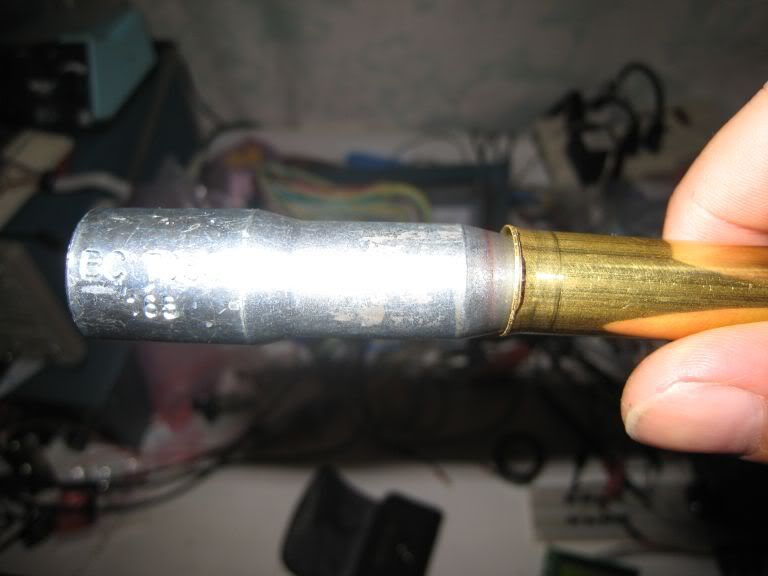
I gave it a leak and pressure test in a sink full of water and it is doing fine. My digital pressure gauge (also from the junk drawer) is acting up, so I am not sure what pressure I got it up to. Enough to get a stream of bubbles coming out of the regulator return line. The regulator was last set to about 40 PSI.
Now I'm a little more motivated to layout a board for the electronics.
Last edited by ollopa; 07-01-2010, 04:27 AM.Leave a comment:
-
Originally posted by ollopa View Post
Rick... That is some very good news... I think you should only work on this project when time and components are handy and whenever you are inspired and inclined to do so. I would be curious to see if you have the same (+) results I got when actuating the ones I was cleaning using the silicone sealed OEM GM Harness... and in those tests...they neither leaked nor shorted during any circumstances. Optimally, the silicone seal compresses tightly, courtesy the metal clips on the harnesses and does a great job of keeping the electrical contacts inside bone dry. I have observed that some of the used/older EFIs I've examined often exhibited rust and corrosion on the two metal tine connectors that seemed to have happened due to long use and/or suffered enough vibration to remove either the cadmium or galvanic coatings on them and expose them enough to cause corrosion. I was just wondering whether or not this would be a side issue to refurbishment that would reduce or change the electrical properties enough to cause a problem...and if so... as an adjunct to a more complete repair of damaged or worn EFIs... I think I might have a fix that would allow for light nickel plating of the tines in a simple manner that would not damage the EFIs and refresh their ability to maintain a good circuit . Many months back...I did some experimenting with electroplating and memorialized the results with images and videos here:

The only concern I wanted to mention was that the injectors might be prone to wear if activated repeated when completely dry... On my end....whenever I had to work with them "dry" I gave them a quick shot of WD-40 when they are first fired up to allow the lubricant the chance to work its way inside and prevent any accidental wear or damage.Last edited by 60dgrzbelow0; 06-28-2010, 05:47 PM.Leave a comment:
-
Well I did some testing and bugfixing today. I had a stuck injector that had already been through the ultrasonic cleaner and a heated soak in degreaser. I was able to get it unstuck by connecting it to my prototype and taping it on my desk upside-down. After a few taps it started to open a little, and then slowly the buzzing became more pronounced and it opened fully. I drove a couple other injectors for several minutes with good results. I made a little error when I did the design and wound up designing it for 0.05ms resolution instead of 0.1ms resolution. It worked fine with 0.05ms resolution but that's just ridiculous, so I scaled it back to 0.1ms.
Everything is looking good right now. I just need to do a little more coding on the user interface, maybe add a bootloader, and put a board together. I'm going to be really busy the next couple of weeks, so I will work on this a little here and there and probably only check in on the weekends. I think I can have something ready to ship out in about 4 weeks. I'll need to put in an order for some more parts this week.Leave a comment:

Leave a comment: