
-
I check my 1990 STE 3.1 today, and it has the big red wire. It goes to the starter under a seperate fusible element. Basically, my alt has 2 wires going to the starter (one from the plug, and the other from the stud). -
Not required, but perhaps a diode in front of it would help protect it from any reverse spikes going through the car's 12v system. A capacitor between 12v in and ground might help dampen any swings in voltage too. Not sure if swings in voltage would be too fast for the regulator to react to or not.Leave a comment:
-
http://www.radioshack.com/product/in...tId=2062599&cp
do i need any buffer or anythign else for this circut? 12v, ground and it puts out 5v?Leave a comment:
-
I say follow Isaac's advice. 5v regulator to ignition on and alt switch.Originally posted by merlot566jka View PostLeave a comment:
-
i taped into the map, it works. but ive got some map problems now...lol. there are other 5v refernces on my ecm that rarent used anywhere, ill try those in a bitLeave a comment:
-
Taping into a 5v ref that goes to a sensor might be a bad idea. You can go to radio shack and get a 7805 5v regulator and hook that up to send 5v to it instead.... Just set it up to power up on key on...Leave a comment:
-
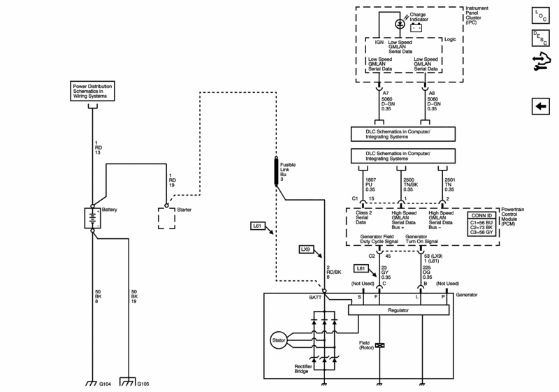
needs 5 volts to turn the gen on at term L. then term f is not used and the gen to guage will just be any b+ signal
i just need a 5 volt ref, like say the tps or map's 5v ref signals. as lont as the ecm is on the gen will be on....Last edited by merlot566jka; 12-16-2007, 01:36 PM.Leave a comment:
-
Document ID# 1459957
2005 Chevrolet Malibu
--------------------------------------------------------------------------------
Charging System Test
Step
Action
Value(s)
Yes
No
1
Did you perform the Diagnostic System Check - Vehicle?
--
Go to Step 2
Go to Diagnostic System Check - Vehicle in Vehicle DTC Information
2
Important: The battery must be above a 70 percent state of charge. Refer to Battery Charging .
Did you perform the Battery Inspection Test?
--
Go to Step 3
Go to Battery Inspection/Test
3
Install a scan tool.
Start the engine.
With a scan tool, command the GEN-L Terminal OFF and ON.
Observe the Ignition 1 Signal parameter.
Does the voltage change with each command?
--
Go to Step 4
Go to Step 8
4
Turn ON the following accessories:
- Headlights (high beams)
- Air Conditioning (A/C) on Max
- Blower fan (on high)
- Heated seats (if equipped)
With a scan tool, observe the Ignition 1 Signal parameter in the engine data list.
Increase engine speed to 2,500 RPM.
Is the voltage within the specified value?
12-15.5 V
Go to Step 5
Go to Step 6
5
Turn OFF all accessories.
Turn OFF the ignition.
Caution: Make sure that the load is completely turned off before connecting or disconnecting a carbon pile load tester to the battery. Otherwise, sparking could ignite battery gasses which are extremely flammable and may explode violently.
Connect a carbon pile tester to the vehicle.
Important: When measuring generator output current, be sure the inductive probe encircles the generator output wire.
Connect an inductive ammeter probe to the output circuit of the generator.
Start the engine.
With a scan tool, command the GEN-L Terminal ON.
Increase engine speed to 2,500 RPM.
Adjust the carbon pile, as necessary, in order to obtain the maximum current output.
Is the generator output greater than or equal to the load test value, as specified in Generator Usage ?
--
Generator OK
Go to Step 7
6
Is the voltage measured greater than the specified value?
15.5 V
Go to Step 12
Go to Step 7
7
Leave the vehicle accessories ON or maintain load test value.
Maintain engine speed at 2,500 RPM.
Measure the voltage of the battery.
Measure the voltage between the generator output terminal and the generator metal housing.
Is the voltage measured at the generator within the specified value of the battery voltage?
0.2 V
Go to Step 14
Go to Step 9
8
Turn ON the ignition, with the engine OFF.
Disconnect the generator harness connector.
Measure the voltage between the generator turn on signal circuit and ground.
With a scan tool, command the GEN-L Terminal ON and OFF.
Does the voltage measure greater than the first value ON and near the second value OFF?
4.7 V
0 V Go to Step 14
Go to Step 11
9
Maintain the engine speed at 2,500 RPM and continue to operate the generator at the load test value.
Measure the voltage drop from the battery negative terminal to the metal housing of the generator. Refer to Circuit Testing and Wiring Repairs in Wiring Systems.
Is the voltage measured less than the specified value?
0.5 V
Go to Step 10
Go to Step 15
10
Maintain the engine speed at 2,500 RPM and continue to operate the generator at the load test value.
Measure the voltage drop from the output terminal of the generator to the positive terminal on the battery. Refer to Circuit Testing and Wiring Repairs in Wiring Systems.
Is the voltage measured less than the specified value?
0.2 V
Go to Step 14
Go to Step 16
11
Test the generator turn on signal circuit for a short or an open. Refer to Circuit Testing and Wiring Repairs in Wiring Systems.
Did you find and correct the condition?
--
Go to Step 19
Go to Step 13
12
Test the generator battery voltage sense circuit, if equipped, for an open or high resistance. Refer to Circuit Testing and Wiring Repairs in Wiring Systems.
Did you find and correct the condition?
--
Go to Step 19
Go to Step 14
13
Inspect for poor connections at the harness connector of the powertrain control module (PCM). Refer to Testing for Intermittent Conditions and Poor Connections and Connector Repairs in Wiring Systems.
Did you find and correct the condition?
--
Go to Step 19
Go to Step 17
14
Inspect for poor connections at the generator. Refer to Testing for Intermittent Conditions and Poor Connections and Connector Repairs in Wiring Systems.
Did you find and correct the condition?
--
Go to Step 19
Go to Step 18
15
Repair the high resistance or open in the ground circuit of the generator. Refer to Wiring Repairs in Wiring Systems.
Did you complete the repair?
--
Go to Step 19
--
16
Repair the high resistance or open in the generator output circuit. Refer to Wiring Repairs in Wiring Systems.
Did you complete the repair?
--
Go to Step 19
--
17
Important:: The replacement PCM must be programmed.
Replace the PCM. Refer to Control Module References in Computer/Integrating Systems for replacement, setup, and programming.
Did you complete the replacement?
--
Go to Step 19
--
18
Replace the generator. Refer to Generator Replacement .
Did you complete the replacement?
--
Go to Step 19
--
19
Operate the vehicle in order to verify the repair.
Did you correct the condition?
--
Generator OK
Go to Step 2
--------------------------------------------------------------------------------
Document ID# 1459957
2005 Chevrolet MalibuLeave a comment:
-
Valeo TG11
Charging System Description and Operation
Generator
The generator features the following major components:
The delta stator
The rectifier bridge
The rotor with slip rings and brushes
A conventional pulley
Dual internal fans
The regulator
The pulley and the fan cool the slip ring and the frame.
The generator features permanently lubricated bearings. Service should only include tightening of mount components. Otherwise, replace the generator as a complete unit.
Regulator
The voltage regulator controls the rotor field current in order to limit the system voltage. When the field current is on, the regulator switches the current on and off at a rate of 400 cycles per second in order to perform the following functions:
Radio noise control
Obtain the correct average current needed for proper system voltage control
At high speeds, the on-time may be 10 percent with the off-time at 90 percent. At low speeds, the on-time may be 90 percent and the off-time 10 percent.
Circuit Description
The generator provides voltage to operate the vehicle's electrical system and to charge its battery. A magnetic field is created when current flows through the rotor. This field rotates as the rotor is driven by the engine, creating an AC voltage in the stator windings. The AC voltage is converted to DC by the rectifier bridge and is supplied to the electrical system at the battery terminal.
When the engine is running, the generator turn-on signal is sent to the generator from the powertrain control module (PCM), turning on the regulator. The generator's voltage regulator controls current to the rotor, thereby controlling the output voltage. The rotor current is proportional to the electrical pulse width supplied by the regulator. When the engine is started, the regulator senses generator rotation by detecting AC voltage at the stator through an internal wire. Once the engine is running, the regulator varies the field current by controlling the pulse width. This regulates the generator output voltage for proper battery charging and electrical system operation. The generator F terminal is connected internally to the voltage regulator and externally to the PCM. When the voltage regulator detects a charging system problem, it grounds this circuit to signal the PCM that a problem exists. The PCM monitors the generator field duty cycle signal circuit.
Charging System Indicator
The IPC illuminates the charge indicator in the message center when the following occurs:
• The PCM detects that the generator output is less than 11 volts or greater than 16 volts. The IPC receives a class 2 message from the PCM requesting illumination.
• The IPC determines that the system voltage is less than 11 volts or greater than 16 volts. The IPC receives a class 2 message from the body control module (BCM) indicating the system voltage.
• The IPC performs the displays test at the start of each ignition cycle. The indicator illuminates for approximately 3 seconds.
• The ignition is ON, with the engine OFF.
from gmdealer worldLeave a comment:
-
ok to update...terminal l is def for the dummy light. the 10ga red wire connects back to the same wire thats on the stud of the alt. so terminal f is only thing left to figure out what it does or needs.Leave a comment:
-
RED and GRAY sounds like the 1999 Grand Am setup. I will take a look and see what I got. I will even scan the 1999 Grand Am books. It kinda makes sense that they would be similar. I believe the 3500 cars use a BCM like the Grand Am, so it only makes sense that the PCM setup would be the same.
Do you know the YEAR, MAKE, and MODEL that your engine came out of?Leave a comment:
-
thanks, i have the connector with the red and gray wire...there like 18-20 guage wire.... no where close to what mine had. ill look more tomorrow...wifes getting pissyLeave a comment:
-
I think all of my cars have different wires. As for the BIG WIRE in the alt connector, that..... hmm.....
Okay. I current have my 1988 Cutlass Supreme, 1989 Cutlass Supreme, 1994 Cutlass Supreme, 1996 W-body, 1997 G-body, 1999 N-body, and 2002 W-body books on my bed, and almost all of them list something different.
The one thing that is consistant is the ones that have the big wire (either red, or orange), it goes to some sort of power supply (fuse block, fusible link).
Tomorrow, I am going to try to get over to my mothers house. I have her truck, and need to take it back to her anyways. I will take a look at my cars and see what has what, and what goes where. If I have a pic of a setup like yours, maybe I can find something out better. As of right now, all of my books say different things.
Grand Am 3400 has a RED, and a GRAY wire going to the PCM (RED is for generator terminal L monitor/control [ie dummy light] and GRAY wire is another PCM input. There is also an ORANGE wire that goes to the underhood wiring harness junction block.
I will see if I can get a better idea after checking my cars. I know one of them has the big wire.Leave a comment:
-
well what i found in the salvage yard was many diff alts on the 660's this is a new connector for the 3500, using only two wires but its the same connector that was used on other gm cars. i got my connector from a sunfire.
the 3500 alt uses only pins b and c of the connector. some other gms used a third terminal in there. the connector has 4 pin capability. they are all inline...like so... ∙ ∙ ∙ ∙ the ones i saw on the 3100s and 3400 were different, like so - ∙ ∙
heres my problem...i have a big red wire on my CONNECTOR. its about 10 guage. what was that for? where does it go now??Leave a comment:
Leave a comment: