Getting the fittings in there will be tough-that's pretty much the only reason. Right now I'm looking at 1/2" steel hardline with inverted flare fittings, and the minimum bend radiuses are going to be violated in a bad way.
The other issue is getting the hardline through the intake wall, there isn't a flat spot big enough for two bulkhead fittings unless I go in the "tunnel" area, which is going to have some flow balance implications. When I get the intake back tonight I'll mock up a few things and see what I can make happen.
-
 Guest repliedWhat about just using some (metal) hard line, with flare or inverted flare fittings to be inside the intake.
Leave a comment:
-
I measured it actually in the intake just above the port opening, which did not change. The guide boss was slightly smaller MCSA, but the valve guide area varied significantly between all six ports. My set of castings were pretty wonky, I was surprised since all the new GM castings I've worked on have been nice. The majority of the port work is in the valve guide area, that's where I found the biggest flow gains and so I went with them. The short side turn is way touchy on these, a little bit went a long way, and was the hardest part to get to "match" between the ports. Second biggest issue so far is the intake-Best I have done with the intake bolted up was ~214CFM at 0.500" lift. Exhaust ports are proving to be a real bear-I've gained less than 8%. They still move enough to satisfy me, so I best quit complaining and just run it.
I am wondering how the intercooler core is going to affect port-to-port flow, but I won't be able to really test that until I get the plenum milled. And I need to figure out water connections-I don't want to run rubber/plastic hoses in the intake due to fuel degrading them over time. O-ring fittings would be the nicest way. I may settle for teflon hose but it's so hard to get it to stay on a hose barb that it seems too much of a risk, too. So far, polyurethane seems to be the best bet for that application, but I am not sure how soft it would get with the sustained intake temps at 160-180F. Nylon tube may work as well, not sure yet.Leave a comment:
-
Where did you measure the MSCA? I came up with it being where the guide protruded in the port, and your modification cut that down significantly.Leave a comment:
-
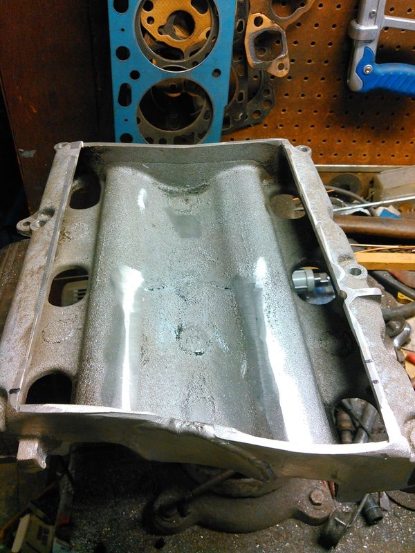
I had to order a different USB->TTL converter because the first one I ordered was a brand that won't talk to the GM ECUs, so while I wait on that to show up, I worked on the intake manifold some more. Technically, at this point there is no reason why this intake won't work on ANY 3500 or big-port 3400, as the lower intake doesn't need to be modified at all.
First thing to do is get it cleaned up a bit and start measuring how far off I was with the angle grinder.
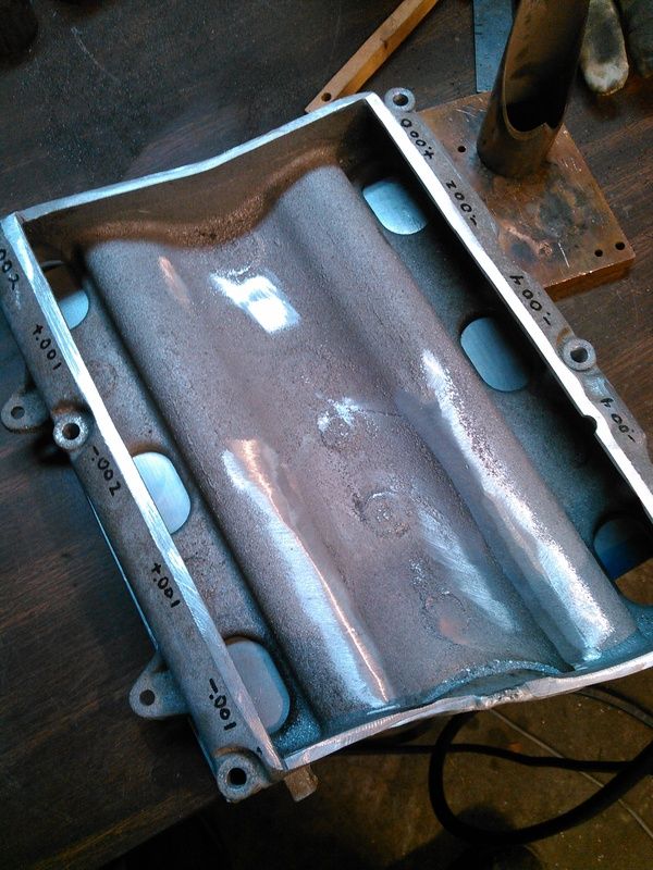
It was +/- 40 thou, spent thirty minutes with a file and got it to this point:
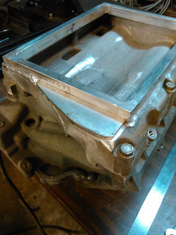
Then I welded up this frame, it's 0.750" tall and 0.500" thick bar, and it actually came out pretty square. A little clean-up on the welding and it was ready to be welded to the top of the intake casting.
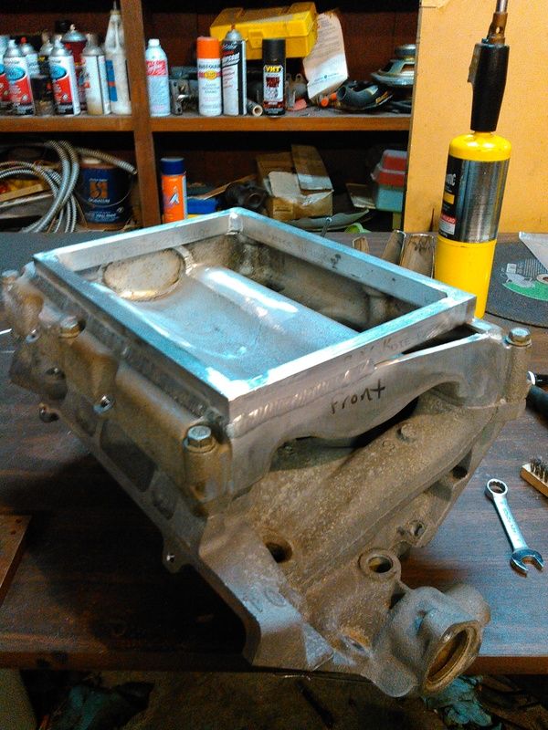
Yes, I did fuck up. The sharp-eyed ones of you will notice that the intake says "front" and the frame says "back". No, it doesn't matter.
The small hole in front was easily filled in, didn't take any photos. The bigger hole in the back I did take some photos of.
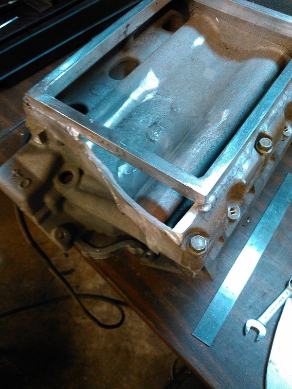
I used some 0.213" thick plate that was in the big stack from page 1, it's thicker than the casting but I didn't have anymore of the 0.127" plate I used on the front. It'll be fine.
When I'm not welding on shitty castings, I can go OK with the TIG with a little rum in me. None of that white rum shit, though.
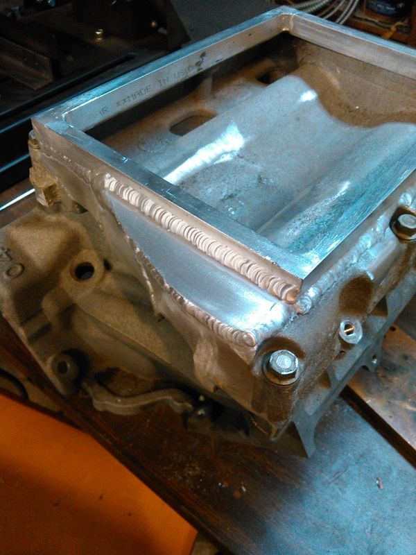
Now that the frame is welded on, I unbolted it from the lower intake manifold and measured how far it sprung during welding. The total out-of-flat was decent, pulled 0.013" total. That's totally workable, I'm gonna run it over to a buddy with a milling machine and have him skim it flat. Yeah, I *could* do it in the shop but the machined face on the bottom is slightly higher than the lowest part of the intake, so I'd have to find two slabs of plate that are parallel and flat, fit them both on the surface plate, and lap the intake against the plates...just more trouble than it's worth. Once the intake is flat and parallel then I'll start drilling and tapping the 20-something holes in the frame on top, that the supercharger plate will be bolted to. Once the plate is bolted down, I'll have to get the heads on the block and the lower intake manifold fitted, and get all the accessory drive bolted up, so I can get the supercharger drive pulley aligned and square. Once that's done and the super is fitted to the top plate, I can start on the headers.
There's no exterior differences between the 3.4L aluminum-headed hybrid I'm building, and the 2.8L iron-headed boatanchor in the truck, aside from the accessory drive. Originally, when the 3.4L engine still had iron heads on it, the exhaust manifolds were identical. I've dummied up the headers in PVC on the truck, so I'm pretty sure I won't have to clearance the truck with the BFH later when I go to bolt the new engine into place. If I have to apply the BFH, well, then I have to apply the BFH.Leave a comment:
-
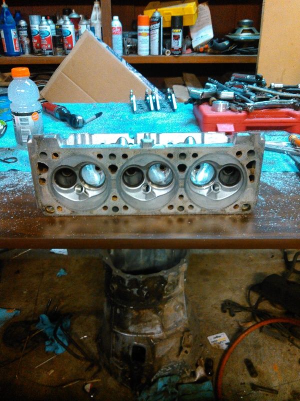
Ok, transmission is out of the shop. Headers are on the operating table and hope to have them finished and shipped by next saturday. Then the heads go back on the bench to see what I can get out of the exhaust ports, get them cleaned up and sneak a little more flow out of them.
Once the ports are done, I'll see if the valves will lap back in (they should, seats are a little pitted but nothing major and no porting gouges so fingers crossed) and if they will, I'll surface the heads and start assembling the bottom end of the engine. I have a heat-treat oven and have made custom bolts before so we'll see-I might have to machine some four-bolt main caps.Leave a comment:
-
Glad to see I'm not the only one that has the bug... Mine is going to get more internal engine mods and serpentine belt set up this winter.
v6super.jpgLeave a comment:
-
I've got a transmission in bits on my work table, followed by a stainless steel header that has to be made, so there won't be a lot of updates on this for a few weeks. When I get back to this, I'll be fixing up the accessory drive, test-fitting accessories and valve covers, and making headers. Maybe a bit more on the intake manifold before the headers, though.Leave a comment:
-
Found a new cleaner for my aluminum parts-works pretty sweet. Zep Orange Clean, doesn't contain any of the acids or bases that cause the white-powder corrosion on aluminum. Works best for me heated to about 120F, so hot tap-water hot. Literally strips away grease and oil soaked into the pores, but doesn't get real deep-it will NOT replace a bake-out or torch-heating for weld prep. Found that out doing the valve cover, had to weld a 6mm thick plate over an old PCV hole so I can fit a new PCV valve, the original was riveted into place and was a known issue with the engine in its OEM application. By heating the parts up to 200F or so and washing in room-temp Zep, the grease got stripped out to welding-clean. Still didn't remove the intake port tar, but it did convert it to a crispy, flaky carbon-like deposit, that brushed out pretty well.
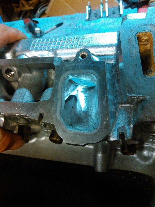
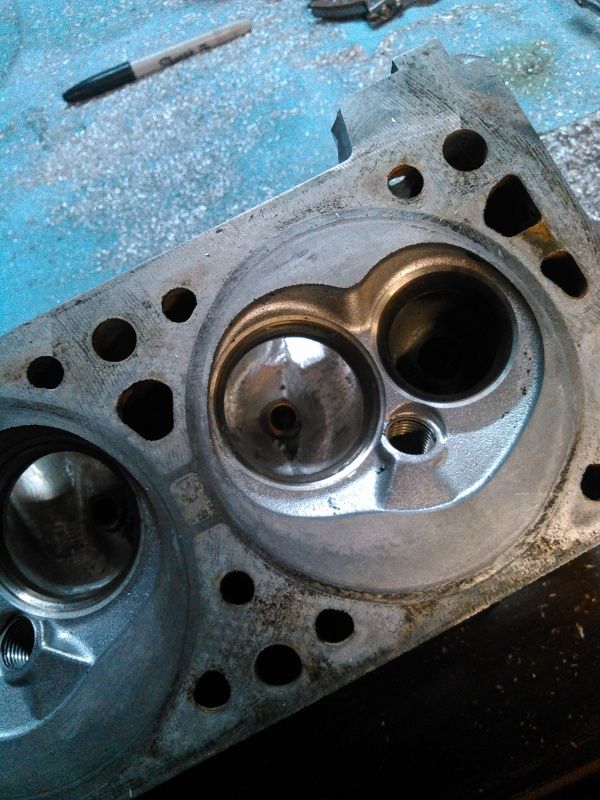
Since the heads needed a valve job anyway, I set the flow bench up in %Flow and started working on the intake port. I still don't have my calibrated venturis made, so I can only measure gains against the fixed orifice plate. I have what the stock heads flowed on a different bench on a different day, but using a clean valve and clean stock port, on the factory valve job, I set a baseline, then worked the port to produce a fair increase in flow while only removing 2.1CC's of material. Low-lift flow didn't suffer any, flow at 0.250" lift picked up 14%, and flow at 0.500" lift picked up 16%. Port is a little howly at 0.500" lift. At 0.550" lift it is louder, same pitch, and flow only picks up about 4% over stock. At least it didn't loose any! Stock, the port was quiet at all lifts. I did not open the gasket face of the port up any at all, MCSA is unchanged from stock. Mostly reduced and re-shaped the valve guide boss, the rest of the port just needed a little cleaning up of casting flaws around the valve seat. Port hasn't been cartridge-rolled yet, so it's right off the carbide. I didn't nick up the stock seats, so this is all on a stock valve job so far. The combustion chamber needs some attention, lots of sharp edges left over from the factory seat cutter, basically a sharp ring all the way round the valve on the intake. Exhaust valve has a nice smooth cut though, on most of the chambers. I will clean off the sharp edge and that's it for the chamber.
Found out that Comp Cams PN 26986 springs will fit the stock seats/seals/retainers, which is nice. These springs are made by PAC, as the model PAC-1286, and also sold as Scorpion Racing SRP-1286. They seem to be a universal spring with a 1" ID and 1.45" OD at the base, and with the 0.650" ID at the top, LS1-style retainers work too. LS6 springs can be made to fit by using LS spring seats with the ID opened up, plus some 4-cylinder valve seals, but lift is limited to 0.490" before coil bind becomes an issue...I would have thought they would do better than that. Installed height is shorter by 0.060" though so it shouldn't be a surprise. The Comp springs are slightly over budget at this point, but something will have to happen, as the stock springs checked out all over the place for spring rate...out of 12 springs, the deviation from mean was 22%.Last edited by Xnke; 08-11-2015, 06:45 AM.Leave a comment:
-
The difference being that the NV3550 from the Dakota is almost certainly going to be a direct-fit, there is no mucking about with mounts or anything. I just measured one and with the exception of the slip yoke, which wasn't in the truck, the shifter lines up, the slave and throwout bearing is the same, and the mounting points are the same. I have a 2.5L dakota clutch disk in the shop so I can see if it'll fit in the stock S10 clutch stack, if so then no need to swap the input shaft.
It's rated for 300ft-lbs input, but it was also fitted behind 5.9L V8s and the like. The few NV3500 internals I have laying about are almost identical to the FS5R30A you're using, as far as size and material, and the case is actually heavier cast. I don't see any reason why it would not be just as strong, although I have no proof either way yet. The R154 is just an AX15 with a slightly rearranged case and optimized gear ratios. Most of the "strong" parts in the R154 are workable in the AX15 case. Don't even try with an AW4/AW5/AX5...they're T-5 level transmissions.
Potentially the MA5/AR-5 from the Solstice/Sky/Colorado/Canyon would work, it's essentially an AX15 and I have seen turbo Skys run 400+HP through them. It shifts like a dream, too...Would need the Dakota bellhousing to fit it up. Might have the shifter wayyyya far back but it is a usable trans for the RWD swaps of the V6-60. Has triple-cone synchros, which aren't particularly appealing from a performance standpoint, but I'm not racing this truck.
The FS5R30A I have right now is strewn all over the shop for modification and rebuilding...Be careful with the 2nd gear shift and absolutely do not put anything rated GL-5 in the box...it WILL eat the synchros in 10-12k miles and 2nd will start grinding irreversably. Even the new upgraded synchro assembly doesn't fix the issue completely. It's an issue of full-size truck gears combined with sports-car style shifting feel that make the synchros susceptible to damage, they have to work hard to control the rotating mass, it's REALLY easy to push through the synchro. Also, the pressed-on engagement teeth are thin and slamming gears will break them off, can't abuse the shifter like the 'ol FS5W71C...you can literally break the shifter off and not damage the engagement teeth on that box!Last edited by Xnke; 08-11-2015, 12:47 AM.Leave a comment:
-
Guest repliedYep, although some guys have used just that bellhousing with an R154, for even more holding power. http://www.thirdgen.org/forums/v6/66...on-option.html
I went with a Z32 trans and made an adapter plate for my conversion. I didn't like how wide the reported power handling range of the R154 or equivalent transmissions was. Anywhere from 400 to 700 hp, where as the FS5R30A has been known to take up to 700 HP no problem in the heavy Z32.
I did look at the AX-5 and AR-15 recently to see if I could find a more easily bolted up solution, but the transmissions were either pricey or seemed to have an undetermined (or low) power handling rating.Leave a comment:
-
Worked out a transmission solution for the aging, ailing, T-5 that is in my truck. Any 96-00 Dodge Dakota 2.5L manual transmission can be bolted up, with some driveshaft/mounting bracket work, and the clutch disk needs to be a 14 spline disk instead of a 10...or I could strip the input shaft out of the case and exchange it for a Jeep input shaft, as it would then use the stock clutch disk.
This nets me a 2WD 5 speed manual transmission with decent strength, as opposed to a known weak T5. It's actually an NV3500 transmission, same as what GM fitted behind the 4.3L in the 94+ S10 trucks, so it should be strong enough.Leave a comment:
-
Guest repliedFor heater core lines, use the inlet on the waterpump for one hose and attach the other hose to a fitting just behind the thermostat. On my 3500 lower I welded a 1/4" plate onto the lower intake, where the temp sensor is located on the earlier gen3 intakes (3100/3400) and drilled and tapped it for 3/8" NPT, then added a an NPT to pipe nipple to connect the other hose. On the opposite side of the thermostat housing, I tapped this existing hole for 1/2" NPT and then used a pipe bushing to thread in the coolant sensor. This is a 3 wire sensor from a 3400 (other engines use this same sensor), this allows for independent connections to the ECM and the gauge. This is exactly how my S10 was connected with my 3.2L hybrid. I'm using the same sensor in the Datsun, but just not using the gauge connection, though eventually I will be once, I get my gauges made up. For now though, I installed the probe for my mechanical gauge in the spot where the bypass tube was originally connected. I also changed to a 160* T-stat, that does not have the extension to restrict the bypass.
ThermostatHousing01.jpg
You can use a serpentine S10 water pump and retain the engine driven fan if you desire. I'm in the opposite boat, I have an S10 water pump, but would really like to run an F-body water pump, to gain a bit more clearance to my turbo and Y-pipe. *shrug*
That's an interesting use of a PC cooling rad.Last edited by Guest; 08-10-2015, 01:27 PM.Leave a comment:
Leave a comment: