 Tweet
Tweet
There have been a couple of guys who wanted to know how to read a compressor map. Hopefully, I haven't made any mistakes this time (unlike the last) and this will prove to be useful to you in your understanding of a compressor map.
Reading a turbo map isnt as difficult as it looks. The map displays 4 key pieces of information.
A. It displays the pumping efficiency of the compressor (meaning the amount of actual air that it pumps in contrast to the amount of heat that's created while wasting energy)
B. The physical amount of air that it can move in pounds per min (just like it says, how much air per/ min)
C. The pressure ratio of the air being pumped (that is, the ratio of pressure that it is capable of that pumping in contrast to the ambient pressure of the atmosphere surrounding it).
D. The surge limit... the danger zone for a turbo whereas torsional pressures and heat can become nasty enough to bend turbine blades.
Lets take a look at a typical map. We'll start with one of my all-time favorite turbos, the venerable GT3582r! Yummy!!

Nice huh? Looking at the map, we can see that its capable of moving 60lbs per/ min as indicated by the "lbs/min" bar in the bottom of the map going from left to right. It takes 1lb/per min to produce 1hp min. So, we can say that this particular turbo is capable of pumping 600hp worth of air max.
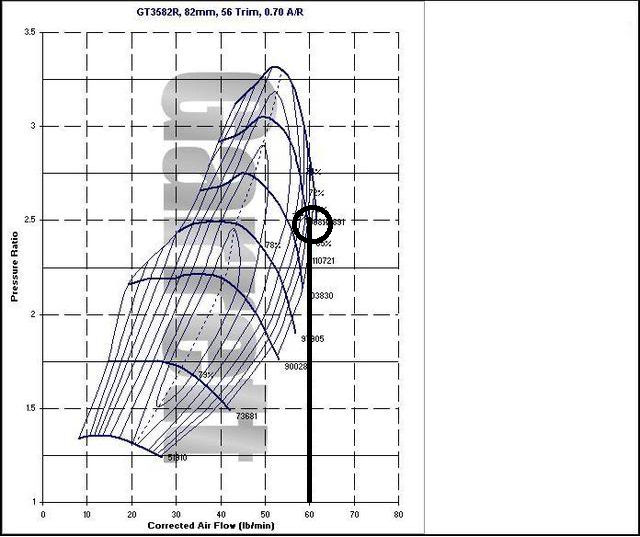
So far, we only know now that the turbo can move that amount of air. Now we need to figure out how we determine the pressure or "boost". The pressure ratio, as shown on the left side of the map, shows the boosted pressure. At sea level, the pressure is 14.7psi. If youre looking at a boost gauge, this amount of outside air-pressure will not be present on the gauge and will read zero psi. Its only when the pressure rises higher than 14.7 that you will see the boosted pressure. So we can define the "P.R." as a multiplying factor used to determine the amount of actual boosted pressure entering the engine.
Heres a little formula. (P.R. x 14.7)-14.7= boost pressure. Lets assume the the p.r. is "2" (remember, actual pressure= boost + atmospheric pressure)
Now we know how to read both the pressure ratio and how to determine the amount of air that can be pumped. The next thing to determine is the efficiency of the compressor. You will notice these little islands that are displayed on the map. These islands represents the amount of efficiency that a particular amount of air can be pumped at a particular pressure. Lost efficiency= increased heat in the pressurized charged, which ultimately equals a drop in air density, less oxygen content and increased chance of detonation. Remember, the amount of boost, DOES NOT indicate the amount of air being pushed into the engine. (Pressure and air-volume have no direct relation to one another).
Youll notice that the efficiency numbers of the smallest islands are the greatest (around 79%), while the efficiency drops in the subsequent larger islands on the map. Ive highlighted the zone with the most amount of air that the compressor can pump at max 79% efficiency. The magic number seems to be 2.4 P.R. x 44lbs per/ min for this particular model. (roughly 440hp at 20.58 lbs of boost)
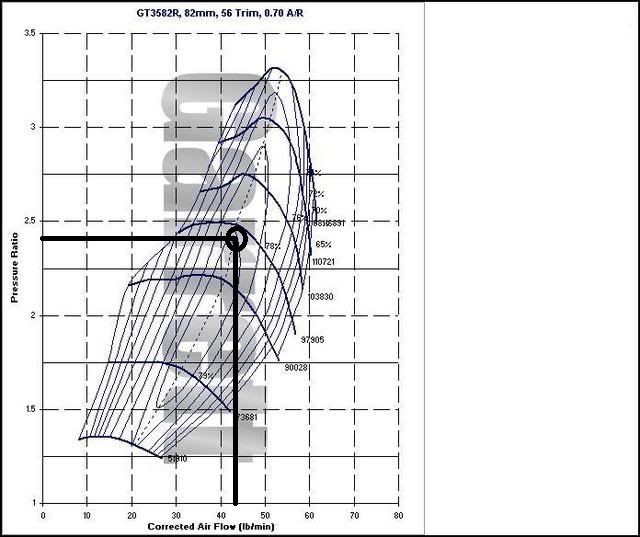
This compressor can pump more air but the efficiency soon begins to drop past this point with the increase in volume. This is the reason why some turbos seem to make more power with less boost and some turbos seem to make less power with greater boost pressure. So the next time someone says anything about "how much boost?" you'll see why the people who know better start shaking their heads
With that being said, heres a compressor map of a turbo thats being used on my roomate's project 5.3l camaro. I've detailed some basic information.
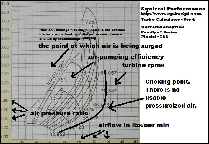
The far left of the compressor map has a zone marked as the surge limit. This marks the area where the turbo can get damaged. Air will build pressure and store energy like a spring which will begin to exert torsional forces against the shaft that can bend turbine blades if that torsional force becomes to great. This happens where the turbo is producing boost, but the engine cant consume the air. When that happens, the pressure builds until it starts being forced back through the housing. you can hear the fluttering sometimes as big-turbo drag cars are starting to stage. That fluttery sound that you hear from a turbo system right before the BOV opens is "surge". It may sound cool, but its NOT your friend.
The choke zone is the area to the far right where the compressor isn't making enough making enough volume and is just wasting energy. (Its identified in the pic as the curved line I drew). The areas of crappy efficiency on the map are just as bad. Over spooling the turbo to try and get more boost past this point is pointless. Its good to try and plot a boost curve that will stay well within a good efficiency range. The GT3582r turbocharger seems happy pumping 50 lbs of air at 3.0 p.r., so 500hp at 29 lbs of boost seems to be reasonable for this turbo.
This T88 in the diagram is able to move nearly 110lbs of air at 3.0p.r. That equates to 1,100hp worth of air at 30lbs boost with room to keep going!!! So like I said... "boost" means nothing by itself.
To sum it all up, the compressor maps allows you to scope the reasonable amount of air volume x pressure for your application.
Reading a turbo map isnt as difficult as it looks. The map displays 4 key pieces of information.
A. It displays the pumping efficiency of the compressor (meaning the amount of actual air that it pumps in contrast to the amount of heat that's created while wasting energy)
B. The physical amount of air that it can move in pounds per min (just like it says, how much air per/ min)
C. The pressure ratio of the air being pumped (that is, the ratio of pressure that it is capable of that pumping in contrast to the ambient pressure of the atmosphere surrounding it).
D. The surge limit... the danger zone for a turbo whereas torsional pressures and heat can become nasty enough to bend turbine blades.
Lets take a look at a typical map. We'll start with one of my all-time favorite turbos, the venerable GT3582r! Yummy!!
Nice huh? Looking at the map, we can see that its capable of moving 60lbs per/ min as indicated by the "lbs/min" bar in the bottom of the map going from left to right. It takes 1lb/per min to produce 1hp min. So, we can say that this particular turbo is capable of pumping 600hp worth of air max.
So far, we only know now that the turbo can move that amount of air. Now we need to figure out how we determine the pressure or "boost". The pressure ratio, as shown on the left side of the map, shows the boosted pressure. At sea level, the pressure is 14.7psi. If youre looking at a boost gauge, this amount of outside air-pressure will not be present on the gauge and will read zero psi. Its only when the pressure rises higher than 14.7 that you will see the boosted pressure. So we can define the "P.R." as a multiplying factor used to determine the amount of actual boosted pressure entering the engine.
Heres a little formula. (P.R. x 14.7)-14.7= boost pressure. Lets assume the the p.r. is "2" (remember, actual pressure= boost + atmospheric pressure)
(2 x 14.7= 29)-14.7
(29.4)-14.7=14.7
boost=14.7
(29.4)-14.7=14.7
boost=14.7
Now we know how to read both the pressure ratio and how to determine the amount of air that can be pumped. The next thing to determine is the efficiency of the compressor. You will notice these little islands that are displayed on the map. These islands represents the amount of efficiency that a particular amount of air can be pumped at a particular pressure. Lost efficiency= increased heat in the pressurized charged, which ultimately equals a drop in air density, less oxygen content and increased chance of detonation. Remember, the amount of boost, DOES NOT indicate the amount of air being pushed into the engine. (Pressure and air-volume have no direct relation to one another).
Youll notice that the efficiency numbers of the smallest islands are the greatest (around 79%), while the efficiency drops in the subsequent larger islands on the map. Ive highlighted the zone with the most amount of air that the compressor can pump at max 79% efficiency. The magic number seems to be 2.4 P.R. x 44lbs per/ min for this particular model. (roughly 440hp at 20.58 lbs of boost)
This compressor can pump more air but the efficiency soon begins to drop past this point with the increase in volume. This is the reason why some turbos seem to make more power with less boost and some turbos seem to make less power with greater boost pressure. So the next time someone says anything about "how much boost?" you'll see why the people who know better start shaking their heads
With that being said, heres a compressor map of a turbo thats being used on my roomate's project 5.3l camaro. I've detailed some basic information.
The far left of the compressor map has a zone marked as the surge limit. This marks the area where the turbo can get damaged. Air will build pressure and store energy like a spring which will begin to exert torsional forces against the shaft that can bend turbine blades if that torsional force becomes to great. This happens where the turbo is producing boost, but the engine cant consume the air. When that happens, the pressure builds until it starts being forced back through the housing. you can hear the fluttering sometimes as big-turbo drag cars are starting to stage. That fluttery sound that you hear from a turbo system right before the BOV opens is "surge". It may sound cool, but its NOT your friend.
The choke zone is the area to the far right where the compressor isn't making enough making enough volume and is just wasting energy. (Its identified in the pic as the curved line I drew). The areas of crappy efficiency on the map are just as bad. Over spooling the turbo to try and get more boost past this point is pointless. Its good to try and plot a boost curve that will stay well within a good efficiency range. The GT3582r turbocharger seems happy pumping 50 lbs of air at 3.0 p.r., so 500hp at 29 lbs of boost seems to be reasonable for this turbo.
This T88 in the diagram is able to move nearly 110lbs of air at 3.0p.r. That equates to 1,100hp worth of air at 30lbs boost with room to keep going!!! So like I said... "boost" means nothing by itself.
To sum it all up, the compressor maps allows you to scope the reasonable amount of air volume x pressure for your application.
Comment