Announcement

Collapse
No announcement yet.

3.4 swap into 1985 Jeep Cherokee questions?

Collapse
X
 
  • Filter
  • Time
  • Show
Clear All
new posts

  • Canyonero
    replied
    Originally posted by cardana24 View Post
    Grey- Nothing (Caynonaro said it was 5V ref)
    You'll notice that I had a question mark that one...

    You'll want to ground all the grounds to ground... anywhere really. My custom harness has a main ground cable running through it where everything that needs ground ties into. Less mess that way, unless you want to move things around later.

    I'd like the spreadsheet, I think you have my email. Been busy lately, was meaning to do that myself.

    I'll take another look at the thread this evening and see if I can help you out more.

    Leave a comment:


  • cardana24
    replied
    I spent several hours on the jeep last night with the multi meter. I did not connect any more wires but rather tried to figure out what the wires are that I had left. I put all of my information in a spread sheet if any one would like it emailed to them. I have listed all of the wire in each harness and they are in the order you would see them on the harness.
    10 pin white harness
    Tan- B19 Serial Data
    Green/White- B28 Buffered Speed Output
    Dk Blue- B18 2nd gear start mode indicator lamp control
    Green/White- nothing on ecm
    Green- about 10 different pins
    Red- lots of pins
    Tan- lots of pins
    Brown- lots of pins

    4 pin Black harness
    Grey- Nothing (Caynonaro said it was 5V ref)
    Orange- B14,B15 Battery (keep alive memory)
    Black/White- PCM ground
    Purple- Ring terminal in harness

    10 Pin Blue Harness
    Lt Blue- C10 2nd start mode switch signal
    Brown/White- B7 SES indicator control
    White- Nothing (Caynonaro said its for the tachometer)
    Dk Blue- Nothing
    Green/White- A2 A/C request
    Pink- C3 Ignition Feed
    Lt Blue/Black- A18 Brake signal

    10 Pin Grey/Black
    Pink- C12,C14,C16 Injector Drivers Cyl's 3,1,5
    Green/White- B6 A/C compressor clutch Relay control
    Green- C2 A/C Clutch status
    Brown- B3 Secondary air injection system air bypass solenoid
    Brown/tape-B11,B12,B13 EGR# 1,2,3 control
    Pink/tape- B20,B32,A6,C17,C20,C21,C25,C31,C1
    Green- Same as Pink/tape
    Pink- C32, C15,C13 Injector driver Cyl's 4,6,2

    3 Pin Black
    Grey- A31,A30,A17,A1 Various sensor grounds
    Dk Blue- A3 A/C evaporator temp signal
    Black- A1,A17,A31 Various sensor grounds


    Sooooooooo....what do I need to hook up out of all of this stuff. Do I need to hook all of those grounds to something? What about the Injector Driver Cylinder stuff...what's that? Anyone what to help?

    Leave a comment:


  • cardana24
    replied
    Originally posted by Canyonero View Post
    I think the purple one was for the starter sol. I didn't need it. There are also a fair amount of Air Conditioning wires and some Auto Transmission wires that go into the cabin.

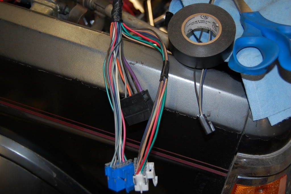
    I'll start with the bottom picture that has the blue white and black connectors.

    Blue Connector:
    Pink and Brown/White - Check engine light
    White - Tachometer (you'll need an adapter, look in my Trooper thread)
    Light Blue/Black - Shift Interrupt (A/T)
    Light Blue - Traction Control (A/T)

    Black Connector:
    Orange - 12v Constant
    Grey - 5v Ref? (that's what I had labeled, don't know what it means)

    Didn't have anything labeled on the white connector.

    The evap solenoid was omitted on my harness. You could live without it. It's not a sensor.

    As for the rest, I'd get the continuity tester out and see where those various wires end up on the ECU connector.
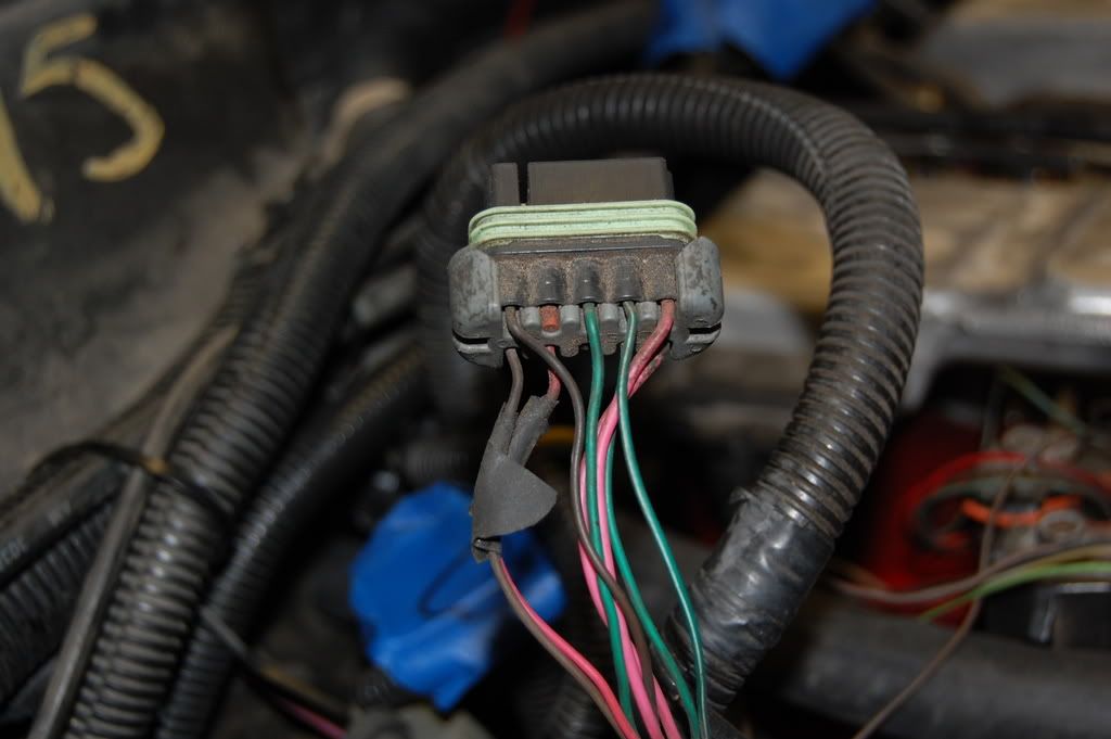
    Okay thanks for that information. I'll look into the tach adapter you are talking about. Do you have a list of the wires that you had to run that were not plug and play sensors with your harness...that's basically what I am down to, if you just have a list I can find those on the ecm then run them to existing wires. Any info on the smaller black plug that is being held down by the e-tape in my picture?

    So does anyone know where the solenoid goes and what it hooks up to? I may try posting that picture on another board since there are not that many people here with the 3.4 running it fuel injected.

    What about the VAC connections on the other side of the PCV hook up on the intake manifold, and also the other side of the brake booster hook up on the intake manifold?

    Leave a comment:


  • Canyonero
    replied
    I think the purple one was for the starter sol. I didn't need it. There are also a fair amount of Air Conditioning wires and some Auto Transmission wires that go into the cabin.

    I'll start with the bottom picture that has the blue white and black connectors.

    Blue Connector:
    Pink and Brown/White - Check engine light
    White - Tachometer (you'll need an adapter, look in my Trooper thread)
    Light Blue/Black - Shift Interrupt (A/T)
    Light Blue - Traction Control (A/T)

    Black Connector:
    Orange - 12v Constant
    Grey - 5v Ref? (that's what I had labeled, don't know what it means)

    Didn't have anything labeled on the white connector.

    The evap solenoid was omitted on my harness. You could live without it. It's not a sensor.

    As for the rest, I'd get the continuity tester out and see where those various wires end up on the ECU connector.
    Last edited by Canyonero; 05-29-2008, 12:02 AM.

    Leave a comment:


  • cardana24
    replied
    I finished hooking a patch wire into the fuel pump power line. and I have pretty much all of the sensors wired but I am left with questions. There is a fatter purple with a ring terminal on the end its close to the knock sensor wiring...I am guessing it is some sort of ground. Where does that go?

    What do I do with the Vehicle Speed sensor wiring? I don't have an electric VSS on my 85 cherokee tranny.

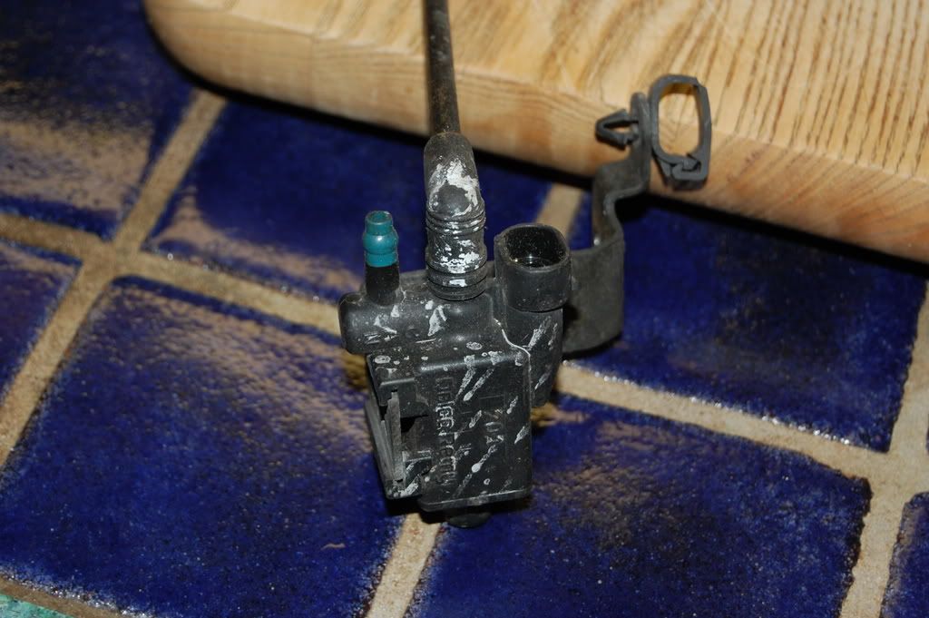
    The sensor that I did not know what it is its the Evap Solenoid sensor(I'll post my picture of it)...where does that go and where do the vac lines go that hook to that.


    Now the fun part. I have taken pictures of several plugs that I assume need to be cut off and I need to run wires to my existing jeep wiring, but the problem is I am having trouble figuring out what these wires are from the diagrams that I have and therefore I do not know where to run them, if any one can help me identify them I would really appreciate it.


    ^^I assume these all hook up inside of the vehicle because there is a big rubber grommet going around the wires, I assume this is where it goes through the fire wall.

    Leave a comment:


  • cardana24
    replied
    Originally posted by Canyonero View Post
    I'm just trying to say that the ECU isn't going to draw the same amount of current as the fuel pump is. You want 12ga to the fuel pump, but the lead going back to the grey wire on the ECU can be 18ga. Look at the attachments, should be able to see what I'm talking about:
    Okay thanks for that. I finish that up tonight. PM me that other wiring stuff we talked about if you get a chance, I would appreciate it.

    I have a few vac lines that I am not sure where they go. One is on the other side of the fitting where the brake booster connects...where should that vac line go? Then the other one that is missing is the line that goes on the other side of the PCV fitting up by the fuel rail. Also why are there vac lines in the wiring harness? Where do they go?

    Leave a comment:


  • Canyonero
    replied
    I'm just trying to say that the ECU isn't going to draw the same amount of current as the fuel pump is. You want 12ga to the fuel pump, but the lead going back to the grey wire on the ECU can be 18ga. Look at the attachments, should be able to see what I'm talking about:
    Attached Files

    Leave a comment:


  • cardana24
    replied
    Originally posted by Canyonero View Post
    Yes, sort of. The 18ga Yellow/White will connect to the Dark Green/White, the 12ga Yellow/White will go to your fuel pump like it says, but you'll also want a small gauge tap back to the ECU grey wire. It's just to inform the ECU that the relay is indeed working and the fuel pump has power, doesn't really need to carry current per say. 18ga would be fine for the tap and it could come right off the relay where the 12ga connects.
    Okay, I am almost done on wiring the fuel relay, I have hooked up everything I can with out having the battery in the vehicle. But I am still not clear on what you are talking about taping the fuel pump turn on line...but not really tapping it. Either I can hook into it and that will draw current or not. I don't get what you are saying that I don't need current per say.

    Leave a comment:


  • Canyonero
    replied
    Yes, sort of. The 18ga Yellow/White will connect to the Dark Green/White, the 12ga Yellow/White will go to your fuel pump like it says, but you'll also want a small gauge tap back to the ECU grey wire. It's just to inform the ECU that the relay is indeed working and the fuel pump has power, doesn't really need to carry current per say. 18ga would be fine for the tap and it could come right off the relay where the 12ga connects.

    Leave a comment:


  • cardana24
    replied
    Originally posted by Canyonero View Post
    There are two wires from the ECU that should connect to the fuel pump circuit. The fuel pump relay control is Dk Grn/Wht (Pin 8 on ECU connector "A", the grey one). Be careful, because there is another Dk Grn/Wht wire on that connector for the AC system (pin 2). Another connector also has two Dk Grn/Wht wires, for the canister purge and the AC Compressor. Sooo, enjoy.

    The ECU also wants to know when the fuel pump is actually running, so there is a Grey wire (Pin 6 on ECU connector "A") that should be wired into a tap coming off the hot side of the relay, the wire running to the fuel pump.

    Also, regarding the knock sensor question. The suggestion I gave of moving the sensor to a different boss on the engine is correct (lower and farther back). That is where the knock sensor is on my old 2.8L.
    Okay let me make sure we are on the same page. Here are the install instructions on the fuel pump relay kit I bought http://static.summitracing.com/globa.../prf-50102.pdf
    The fuel pump relay control is Dk Grn/Wht (Pin 8 on ECU connector "A", the grey one) So y ou are saying this wire should connect to the 18 gauge yellow white wire talked about in step 3? Then you are saying that the Grey wire in Pin 6 A Should be connected to the 12 gauge Yellow/white wire talked about in step 2? Let me know.

    Leave a comment:


  • geoffinbc
    replied
    You can move the knock sensor to either of the block drain locations on either side of the motor. You can also install a 45* pipe elbow and mount it with that if you like.

    Leave a comment:


  • cardana24
    replied
    Can you tell from your wiring which dark blue wire is the VATS wire? I know you have a custom harness, but possibly they wired in a VATS bypass? It's supposed to be a dark blue colored wire. Also thanks for the info on the other stuff, I will look for another location for the knock sensor though I already have cut my motor mount to make that location work, but if the engine moves too much it may snap it off, so I will still check that, do you have a picture of your location?

    Originally posted by Canyonero View Post
    There are two wires from the ECU that should connect to the fuel pump circuit. The fuel pump relay control is Dk Grn/Wht (Pin 8 on ECU connector "A", the grey one). Be careful, because there is another Dk Grn/Wht wire on that connector for the AC system (pin 2). Another connector also has two Dk Grn/Wht wires, for the canister purge and the AC Compressor. Sooo, enjoy.

    The ECU also wants to know when the fuel pump is actually running, so there is a Grey wire (Pin 6 on ECU connector "A") that should be wired into a tap coming off the hot side of the relay, the wire running to the fuel pump.

    Also, regarding the knock sensor question. The suggestion I gave of moving the sensor to a different boss on the engine is correct (lower and farther back). That is where the knock sensor is on my old 2.8L.

    Leave a comment:


  • Canyonero
    replied
    There are two wires from the ECU that should connect to the fuel pump circuit. The fuel pump relay control is Dk Grn/Wht (Pin 8 on ECU connector "A", the grey one). Be careful, because there is another Dk Grn/Wht wire on that connector for the AC system (pin 2). Another connector also has two Dk Grn/Wht wires, for the canister purge and the AC Compressor. Sooo, enjoy.

    The ECU also wants to know when the fuel pump is actually running, so there is a Grey wire (Pin 6 on ECU connector "A") that should be wired into a tap coming off the hot side of the relay, the wire running to the fuel pump.

    Also, regarding the knock sensor question. The suggestion I gave of moving the sensor to a different boss on the engine is correct (lower and farther back). That is where the knock sensor is on my old 2.8L.
    Last edited by Canyonero; 05-26-2008, 10:48 PM.

    Leave a comment:


  • cardana24
    replied
    I worked on some wiring the past few days. I have a lot of it hooked up but I still have plenty of questions. One of my biggest questions is which wire is used for VATS? In my haynes manual it says it is a dark blue wire but it does not tell the pin location. Anyone know? Also there is a sensor that is not currently on the engine. I have a picture of it but my computer is not cooperating right now. It has a two prong electrical connection and two ports for vacuum lines, I am guessing it is some sort of selinoid but I do not know where it goes and what should plug into it.

    With the fuel pump wiring I have soldered the newer plug on, and I have soldered in the hot wire from the relay, but I still need to wire the rest of the relay. Is there a wire from the ecm that I should be running to the relay or should I just find a switched source some where else? That's it for now. Thanks for any help.

    Leave a comment:


  • cardana24
    replied
    Originally posted by Canyonero View Post
    Can it simply be moved to another boss? I really don't know, but it looks like it would fit here:
    I didn't get a chance to work on it tonight, but it really does not want to fit. You need to remember that I am not using the mounts pictured. Those are the camaro mounts. I am using my stock jeep mounts.

    Leave a comment:

Working...
X