Hi there!
NOTE -- I'm working from memory, and I'm more familiar with the older ignition modules than the one on this '95, but I think I'm at least close enough.
The Bypass signal is used to tell the ICM that the PCM will control the timing vs. letting the ICM do it. During cranking the PCM doesn't control ignition timing. The Bypass signal is high (I think, I may have the polarity backwards). The ICM is firing the coils using the crank trigger. Once the PCM sees that engine RPM is high enough that it thinks the engine is running, it pulls the Bypass signal low and the ICM no longer fires the coils on its own. Rather, the PCM uses signals from the ICM to know where the crank/cam is, and pulses the Ignition wire to the ICM when it's time to fire the coils.
If you have spark on all six plugs during cranking (which I think you said you did), I would scope out the Ignition Control and Ignition Bypass lines and verify that they're behaving. Bypass should switch polarity once it starts and you should see a square wave on Ignition Control once it's running. I'd verify this on the van to ensure you know what the signals should look like.
If there is a PCM/wiring fault I'm guessing it's in one of these two lines, though it's possible that the PCM's 3x crank trigger hardware's failed. I think you mentioned the PCM didn't register any RPM during cranking, which isn't a good sign but may be a red herring.
I've got a Camaro 3.4V6 PCM but it's for a 5-speed. 16196742 BPCN I know nothing about its history as it came with the 3.4 I put in my '84 Blazer (running TBI). Let me know if you're interested.
-
"someone point me to a terminal release tool... " . . . . : They can be had from your local Snap-On, Mac or Matco tool guys. You can also get them from electronics supply stores and through your local GM dealer service dept. special tools catalog.Leave a comment:
-
I had a similar issue with a 1987 Buick Century, which has the 3.8 and DIS ignition.
The problem was the terminals in the connector that plugs into the ignition control module. The terminals had spread open so that the contacts were not touching the pins on the DIS module sufficiently to run.
I was able to "spring closed" the terminals with a needle-type terminal pick so that they were tighter on the pins and the engine ran fine afterwards.
I had spent 2 days troubleshooting it before finding this!
Hope this helps, I didn't have time to read the whole thread!
DavidLeave a comment:
-
ah... good point...Originally posted by 86FieroSEv6 View Post
If the ICM doesn't require a signal from the PCM to generate the square wave, I should be able to remove the 6-pin connector from the ICM and clip a probe on the pin in the ICM and see the square wave, right?
Cool... more tools to buy...If you have a terminal release tool (I know, I know, another damned tool you can't live without) you could back out that terminal from the PCM, clip on to it and check for signal.
Those are some really small terminals in the PCM... someone point me to a terminal release tool...Leave a comment:
-
I removed the connector from the PCM and the connector from the ICM. I verified the wires were fine from end to end and that none of them were shorted to ground or shorted between wires/pins.Originally posted by bszopi View PostLeave a comment:
-
"Does anyone know what would prevent the ICM from generating that square wave for the PCM?" . . . What if it IS generating a signal but is shorted out within the PCM? If you have a terminal release tool (I know, I know, another damned tool you can't live without) you could back out that terminal from the PCM, clip on to it and check for signal.Leave a comment:
-
Have you tried to trace the wires from the ICM to the PCM? Is there a chance of a shorted or broken wire, which would therefore cause the signals not to be sent between the 2? I'd say if it works in one vehicle, but not the other, you definitely need to start looking at the wiring.Leave a comment:
-
It's Saturday... the day I waste hours and hours working on the '95 Camaro...
Today, I spent more time with the o-scope than the hand tools
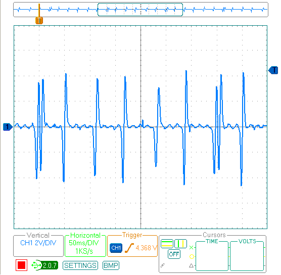
I captured the signal from the 3x sensor across the two wire where they go into the ICM
You can see the six equally-spaced signals and the seventh spike 10 degrees after the sixth. Looks good to me <puzzled look>
I then connected the scope to the signal that is sent from the ICM to the PCM. I got nothing. The ICM isn't generating the square wave signal to the PCM... the signal the PCM determines RPM from... hmmm
Next, I removed the ICM and coils from the Camaro and installed them in my wife's 2002 Silhouette. The Silhouette started right up... <drat!>
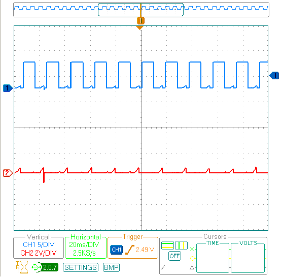
I connected the scope to the signal that is sent from the ICM to the PCM. I'm still struggling with the software for the o-scope, so I couldn't capture the cranking sequence while actually turning the key, so I just captured the signal after the engine was running
The top line is the "high" signal. The bottom signal is the "low" signal. Looks good to me.
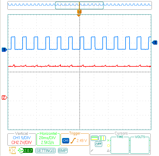
I then connected the scope to the two "Ignition Control" lines from the PCM to the ICM. At first, I turned the key to ON. I saw nothing... both at zero volts. Then I started the van.
The top line in the "Ignition Control" line. It is the square wave that the PCM sends to tell the ICM to fire the coils. Looks good to me. The bottom line is the "Ignition Control Bypass" It is at about 5 volts... just what the documents say it should be during "run".
About now, is when my wife came out to find all my wires under the hood of HER van. I was instructed to put everything back together and leave her van alone. <busted!>
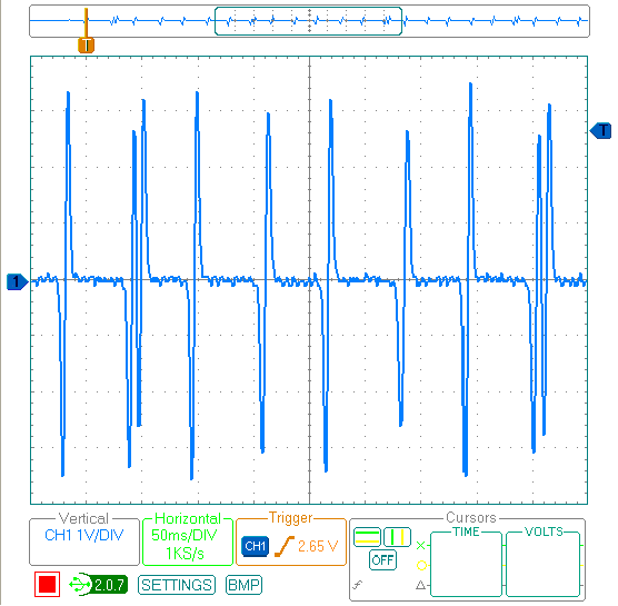
I put the ICM and coils back on the Camaro. Having run out of ideas, I installed the crank sensor I bought last week. The signal at the ICM looks like this:
The old sensor had a bit stronger signal, so I put it back in the car.
Does anyone know what would prevent the ICM from generating that square wave for the PCM? anyone? ideas? guesses? wanna buy a Camaro?
Could it be the Ignition Control signals from the PCM? If they aren't as expected, maybe the ICM doesn't generate the square wave??
Maybe the signal from the crank sensor isn't exactly what the ICM is looking for. Anyone know what it is supposed to look like? I didn't get a chance to log the crank sensor signal on the Silhouette. Maybe tomorrow I can get the kids to create a diversion <evil grin>
Give me ideas...
I'm about 95-percent ready to get the PCM from the salvage yard down the road. If I drop the cash on that PCM, I won't be able to take it back when we discover the problem was really a blown fuse or something silly like that... Yes, I verified the power at the ICM is good...Leave a comment:
-
Could I have killed the PCM?....
As usual, my Saturday is dedicated to Sydni's car <sigh>
I have been reading more in the Factory Service Manual (FSM). I found a troubleshooting chart that helped me realize what should be going on during the start process.... see attached FSM pages
Open attachment page b [i.e. 6E3-A-31]...
Step 1 - I do NOT see RPM changing. All I see in TunerPro is 300 RPM... whether the software is connected to the PCM or not. When I am connected, I see the Coolant temp, TPS and everything else... just no RPM changes.
Step 3 - a couple weeks ago, I had spark at each plug. I discovered that the ones that weren't firing properly had the other side of the coil not grounded <smacking forehead>
Step 6 - I do NOT see RPM jump in scan tool when I quickly tap 12V to the PCM... nothing...
"NO" box below 6 says "CKT 647 open or shorted to gournd or faulty PCM"... swell
I pulled the PCM and the 6-way connector at the ICM. I connected an Ohm meter on each end of the CKT 647... [E on the 6-way and C30 on the PCM]. I have continuity and the wire is not shorted to ground.
I then discovered that a couple of the wires on the back of the 6-way connector were bare <gasp!>
I think the B and C on the 6-way connector may have shorted... <drat!>
I bought a little oscilloscope online. It arrived yesterday. So, to justify the purchase of the scope, I connected it to the 3X crank sensor. Once I got the scope setup right, I could see the equally-spaced six pulses and the one sync pulse... It was cool! I declared the sensor "good"
Tomorrow, I'm going to try to put the scope on each of the pins of the 6-way connector. Maybe that will tell me something... I hope
Can someone explain what the "Ignition control" and "Ignition Control bypass" signals from the PCM are for?
And...
Does anyone have a '95, 3.4, auto-tranny, F-body PCM they can loan me... or sell me cheap?
Thanks again,Attached FilesLeave a comment:
-
-
I think you have it nailed, Tom... It's often easy to forget that these engines have so much going on at all times that is completely invisible to us... but these are busy little M-Effers involving collapsing electromagnetic fields (ICM and Coils) or in some case Hall Effect events ...Square Waves...Sine Waves with the various electromechanical motion sensors... Jesus... and when something goes awry...we all find ourselves staring down under the hoods ...and scratchin' our collective noggins to figure out WTF is really wrong... especially with the OBD-I cars.Last edited by 60dgrzbelow0; 04-18-2010, 01:31 PM.Leave a comment:
-
Bob, there have been a number of people having trouble with those wires. They require a certain number of twists per foot. Don't quote me but, minimum of 3 turns per foot seems to ring a bell. Most PCs use "Twisted Pairs" on some wires. The ground wire twisting around the signal wire isolates the signal wire from interference from other electrical sources. If I remember, it didn't stop the cars from running. It affected the high revs more than anything,,,, I think!!
Remember,,, don't quote meeeee!!!
Tom....Leave a comment:
-
Brad... wasn't there some blurb a while back about somebody accidentally "untwisting" the 3X pigtail-wire...or repairing one without the requisite number of turns in it necessary to prevent EMF interference...and essentially nullifying its signal quality?Originally posted by bszopi View PostLast edited by 60dgrzbelow0; 04-18-2010, 12:05 PM.Leave a comment:
-
What is the engine coolant temp sensor reading? If you don't have a scanner handy, a DVOM (digital volt/ohm meter) on DC volt scale backprobed at the yellow wire should read about 3 volts or so for a cold engine (roughly a half volt for a warmed up engine). Also, a MAF screw up can cause this as well. Try unplugging the MAF to force backup fuel and spark control and see what happens.Leave a comment:
Leave a comment: