Home Made Fuel Injector Cleaning Machine

Collapse
X
 
  • Time
  • Show
Clear All
new posts

  • 60dgrzbelow0
    replied
    Okay... This morning, I assembled only the parts of the "Frankinjector" equipment necessary to perform the Fluid Balance Test on six Rochester Multech EFIs for the VIN "S" GM vehicles. You will note from the photos and videos on this update via my photo-bucket link, that I decided to use the "KISS" Principle on the design of a tray to support the 50ml Graduated Cylinders by using a deep-dished stainless steel, magnetically attachable tool tray to support the collective tubes and simplify the need to build one that I would have to design another quick-on and off mechanism. Because the Fuel Rail has a staggered design, when rotating the Fuel Rail to do first one set of three injectors on one bank and then the other...moving the tray off center as necessary to support the tubes is a snap. Spills are easily captured and contained and so is the cleanup after finishing this test. I left off all the acrylic drain tube plumbing as it was not needed for this testing method and would have actually been a hindrance in getting around for this exam.

    They say you should be careful what you wish for... and in this case, the test(s) did reveal that this one set of injectors does have some performance differences that can only be reconciled by mixing and matching injectors from other sets that more closely fall in line with each other in performance or by further cleaning via the hot-soak in Purple Power and maybe back-flushing (...if I can figure out a way to do it using the existing Fuel Rail). I have one more set of EFIs to evaluate on hand and the other identical set (with fuel rail and electrical harness all for just a ten spot) will be arriving soon. The set up and break down of all this integrated hardware has proven very smooth and easy to handle. When not in use, the acrylic plumbing fits nicely in an over-sized Zip-Lock Bag and likewise for the six Polypropylene Tubes, so that shop dirt and contaminants do not get all over them. Keeping the rack with the rotating Fuel Rail assembly from getting under foot has proven itself very "storage friendly" and the whole upper portion can be covered with a long trash bag to keep the shop dirt from making a mess of this equipment. On the whole, this kind of "One Over The World" idea for the design of this machine has proven itself out at every turn!

    This takes care of the problem of conducting the "EFI Fluid Balance" portion of these comprehensive testing and cleaning procedures. Up next to try and solve is how to isolate and protect the wiring harness from shorting out and making direct contact with the hot cleaning solution when the EFIs are being dunked in the UMAX Ultrasonic Machine...

    A private space for your group's photos and videos. Share, react, and relive moments together. Available on iOS, Android, and desktop. Free for new sign-ups.
    Attached Files
    Last edited by 60dgrzbelow0; 10-15-2009, 01:41 PM.

    Leave a comment:


  • 60dgrzbelow0
    replied
    Okay... on the heels of this morning's inspiration... I set about making the modifications to "The Frankinjector" machine that will now allow me an easy way to do the EFI Fluid Balance Test... and with unbelievable ease, too. Many thanks to all who poked and prodded my thinking here... because in the absence of this collaboration on www/60degreev6/com ... I may not have gotten these ideas in any other way! When I first imagined doing this... I thought about Superdave's parsimonious admonition on "over-engineering" it any further. So I took the simplest route I could think of in using JB-Weld to fix some threaded rods in line with the axis of the Fuel Rail's possible center of rotation. But this wasted about an hour of my time and I abandoned that build for the ones shown in the images and newest video here:

    A private space for your group's photos and videos. Share, react, and relive moments together. Available on iOS, Android, and desktop. Free for new sign-ups.


    That design took a bit longer to engineer because in spite of being a great construction material...Angle Iron (the residue of the sacrificial Bed Frames) is a bit difficult to work with when making parts that have to work in closer quarters than the original standing frame requirement. In any case...I adhered to the idea that once built and installed on the frame... the ability to rotate and adjust the position of the Fuel Rail for any number of reasons had to follow the idea that it would NOT be off center...regardless of the position I needed it to be in. And so...a few hours later...with a bit of labor and measuring thrown in...for "Good Measure"...I give you "The Frankinjector" REDUX version that now includes the axial re-positioning as described in my photos. etc. now on my Photo-Bucket site. I will be anxious to see what you think of this "angle" and let me know if I missed anything that needs more work. To the nearly thousand viewers of this thread... thanks for your patience in watching me stagger around with this while trying to make this idea become real. I think I have had a very good day with this improving the design and functionality of this device! Tomorrow morning...I'll button up all the parts and pieces and introduce the 50ml Graduated Cylinders to the fray (I've got to design a tray of some kind and use the two vacant holes in the cross-member that are now free and and see how things work out).
    Attached Files
    Last edited by 60dgrzbelow0; 10-21-2009, 06:20 PM.

    Leave a comment:


  • 60dgrzbelow0
    replied
    Holy Smokes...! I think I've GOT it!!! I don't know why I didn't think if it B4... All I need to do is add an angled bracket to the threaded support rods and bolt the other end to the two Fuel Rail support holes in the outer cast aluminum block of the Fuel Rail Assembly! Doing it this way would angle the whole Fuel Rail over until the tips of the Fuel Injectors are pointing STRAIGHT DOWN! Moving the Fuel Rail around this dynamically will NOT affect the EFI Cleaner Feed Hose attachment on the Fuel Rail Schrader Valve and will NOT hinder the use of the EFI Electrical harness, either!

    Done!...

    Naturally it would easier if I had some sort of wide support bracket coming through holes drilled on either side of the Vertical Angle Iron Frame Supports. I just need to drill a small hole at the same height in both Upper Frame Arms to be able to feed a steel rod through them, fitted with some simple brass bushings or bearings mounted on both ends there and then somehow attach the rod ends to either side of the Fuel Rail. Then when I want to re-position the whole Fuel Rail Assembly, all I need to do is un-tighten the supporting rod assembly and rotate it back and forth (like a Rocking Chair or maybe a Pig on Barbecue Spit...) to move the Fuel Rail from one vertical position to another for both banks to be able to achieve this proper vertical position! ... but I'll work on that later... at the very least...I can use the pre-angled brackets idea first to get the Fuel Rail positioned just right and test it to see if this will work. Now all that remains is for me to design a sort of Holding Platform to support the 50ml Graduated Cylinders under each EFI Nozzle and turn on the machine and see how they compare! Gentleman...it is great to knock these ideas around with you guys! THANKS!!!
    Last edited by 60dgrzbelow0; 10-14-2009, 10:25 AM.

    Leave a comment:


  • 60dgrzbelow0
    replied
    Thanks for the imagery that explains what you imagined. I was pretty wrecked for lack of sleep last night and failed to remember that in February of 2009, I actually looked at your solution side then and discovered (as the attached photos will display) that I could not make any of this work for several reasons: (1) The tubing material the fuel rails on the later model 3100-3400 GM 60* Engines is made of a plated/coated thin steel that does not lend itself to either bending, brazing or welding without either using an electrical contact welder or Tungsten Inert Gas for reworking the parts into anything I could use for this project.... and ...(2) The in-port interface for the fuel injectors are all either canted or angled and made so close and flush with the main rail piping that even if I could cut them off and attach them to another rail design... I'd FUBAR the welding and ruin them for any good use. As you can see from the dated receipt on my purchase of two NOS style Fuel Rail Blocks from Summit at the beginning of this year...I was trying (contrary to SuperDave's notion that I'm so keen on over-engineering as a means to an end) to come up with something simple, direct and elegant that would also serve the many masters of need for quick disconnect, effective sealing of the fuel pressure ...and most important for the Flow Balance Test... a straight, vertical shooting vector downward for the EFI Cleaner to spray into some six (6) matched, graduated cylinders. In the end...the bevel angled GM Fuel Rail I went with was a compromise that will have to hold until I can re-engineer a better solution. The truth is...I had to do it this way initially so I could at least get something done and prove out the basic design idea of my machine and show the value of it actually working... and now that I know that it does... I am seeking some improvements to match the industrial grade versions in overall capability. Its interesting to find that your collective ideas have paralleled my own, step for step on this project. What I would not give to have the knowledge and access to the materials and equipment that CNCGuy and Forced_Firebird know how to use...
    Attached Files
    Last edited by 60dgrzbelow0; 10-15-2009, 05:40 PM.

    Leave a comment:


  • pocket-rocket
    replied
    My mistake... the fuel rail has 4 hold down bolts...

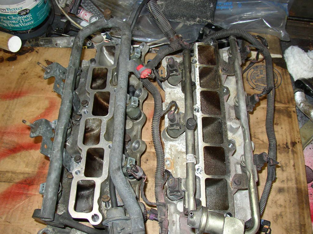
    Here is a nice comparison pic from above of the 91-95 style LIM (on the left) and 96/97 style LIM (on the right, of course). I'm not sure this will help you out with figuring how small it is compared to the other engines LIMs.


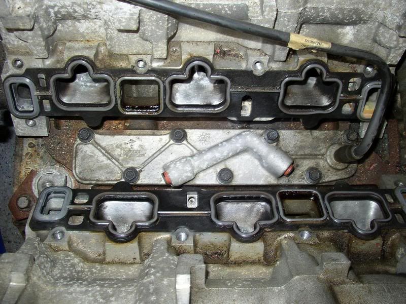
    As you can see by this pic of the heads from above, it mounts down low in the "V"


    If I had to give quick rough measurements, overall I would say it's probably 8 inches wide (from head to head at its widest point), 6 inches tall, and maybe around 22 inches long. These measurements are only the LIM and do not include the fuel rail.

    Leave a comment:


  • 60dgrzbelow0
    replied
    "The Frankinjector" Video Three

    Originally posted by pocket-rocket View Post
    You know... out of all of the 60v6 LIMs, the DOHC is physically the smallest, and has quite large ports in it where you could set your graduated cylinders probably right up to the injector outlets without hacking it up. And the rail for it only needs 2 8 or 10mm bolts to hold it down. BTW, what sort of cleaning solution and solution/pressure tank setup is that you are using?
    I'd like to get some images of what you describe and see what I could make of your great suggestion... I keep thinking that if I can overcome the injector angle issue...probably using more clear Acrylic hosing and some type of rack or stand for the 50ml cylinders...with the means to sort of slip the rig in and out without a lot of hassle in the set-up side...then I'll get it right...but your suggestion is making me look in another direction.

    The cylinder that holds the mixture of EFI cleaning fluids is just a commercial 90 PSI proofed aluminum A/C pressure cleaning cylinder that I removed the A/C low side hose from the bottom where the A/C Flush would normally make its exit under compression and replaced it with fuel proof hoses, a standard inline galvanized steel cannister fuel filter and a brass valve to cut off the cleaning solution fuel prior to reaching the Fuel Pressure Gauge. Notice that everything in the 'tubing loop' cascades downward? That is so whatever residual air there is that gets mixed or pumped or trapped in the system fluid column will boil upwards and wind up on top of the cleaning fluid. Come to think of it...The system that is so similar to mine that I gave credit to earlier in the post...he used some large, galvanized standard plumbing pipe and fixtures...it might be cheaper to build the compression cylinder his way... but I have always been leery of compressing any gas in the confined spaces of galvanized steel or highly brittle, thin cast iron because it tends to detonate and fracture on failure and the pieces that come out are no different than the ones coming from an exploding hand-grenade. When an aluminum cylinder fails...it tends to flex-burst open with a lot less danger to people nearby.

    The first batch of EFI cleaning fluid was about a 50/50 mix of SeaFoam EFI/Carburetor Cleaner and Lucas EFI Cleaner. But that proved to be quite viscous...almost too much so. The batch I made up today; you can see how it performs on the link to the latest video, was a 50/50 mix of WD-40 and Lucas EFI Cleaner. Here is the latest video with more answers to the questions you just posed. Please note that the controversy originally had to do with how to vary the Fuel Pressure in the absence of using a vacuum draw from the design standards for this particular Fuel Rail/Manifold. I wanted to side-step having to mess with it...and I think I have been successful in doing so and still have precise control over the Fuel Pressure before it reaches the EFIs... Here goes nothing:

    A private space for your group's photos and videos. Share, react, and relive moments together. Available on iOS, Android, and desktop. Free for new sign-ups.
    Last edited by 60dgrzbelow0; 10-21-2009, 06:14 PM.

    Leave a comment:


  • robertisaar
    replied
    ah, i thought you meant something like converted from the camera, then dealing with it before uploading...

    i have yet to upload a video to PB, so i'll keep this in mind....

    Leave a comment:


  • 60dgrzbelow0
    replied
    Originally posted by robertisaar View Post
    pre-converted?
    "pre-converted" as in done via the Riva or Avidemux software locally on your hard drive b4 uploading. If you directly load an AVI file up to www.photobucket.com (up to a maximum of 100 Megs per video) the conversion is done by them in two stages and on-the-fly over the Internet.

    First... they accept the upload... then they convert the AVI to the acceptable FLV format as a Flash Video in the smallest video footprint they can get. All of this digital masturbation takes forever and it can literally take hours on end just to get your videos uploaded. Due to the sheer size of their photo/video libraries and the bandwidth that everyone uses to access and function properly on their sites... I guess they try many different storage methodologies to archive what they receive and economize their server storage space...But for the life of me, I cannot calculate how they can absorb well beyond a trillion uploads... or why they even bother doing it. Don't get me wrong... I'm grateful because it allows me the chance to share what I know, what I'm working and my build ideas with so many other people... I'm just confused on the motives of photo-bucket for allowing it to be so.
    Last edited by 60dgrzbelow0; 10-21-2009, 06:11 PM.

    Leave a comment:


  • pocket-rocket
    replied
    Originally posted by 60dgrzbelow0 View Post
    Thanks for the offer...but I'm going to take P-R's idea to bed and think about doing this in similar way to his LIM suggestion ... but with some other pieces of metal I already have on hand. If that idea does not work... I will follow up with you, Mr. "R... Thanks! Please note that I will not be doing the Flow Balance portion of the tests during the Reverse Flushing procedures... but all of these ideas of yours are helping get on the right track. I'm beat right now... and will work this all out overnight while I'm 'sawing logs"...

    You know... out of all of the 60v6 LIMs, the DOHC is physically the smallest, and has quite large ports in it where you could set your graduated cylinders probably right up to the injector outlets without hacking it up. And the rail for it only needs 2 8 or 10mm bolts to hold it down.

    BTW, what sort of cleaning solution and solution/pressure tank setup is that you are using?

    Leave a comment:


  • robertisaar
    replied
    pre-converted?

    Leave a comment:


  • 60dgrzbelow0
    replied
    Okay...the "pre-converted" FLV is uploading MUCH faster (Thanks Mr. "R"...I learned something here...)

    Leave a comment:


  • 60dgrzbelow0
    replied
    Originally posted by robertisaar View Post
    weird.... so it doesn't like the audio encoder that was used.... tried saving it anyways? or is that as far as it can get?
    Okay... I like the Open Source apps a lot for my Linux box builds...but for the sake of time, fatigue and convenience for this Windo$e Laptop...I opted to download and run something called Riva FLV Encoder 2.0... It is completely Freeware..and working like a charm! I'll try uploading the FLV outputted file on this laptop and see if it loads to my photobucket fast.... BRB.

    Link to Riva:

    Leave a comment:


  • robertisaar
    replied
    weird.... so it doesn't like the audio encoder that was used.... tried saving it anyways? or is that as far as it can get?

    Leave a comment:


  • 60dgrzbelow0
    replied
    About the AVIDEMUX APP... I'm getting this error when loading the raw AVI video as saved in my Sony Cybershot camera (see attached screen print)
    Attached Files

    Leave a comment:


  • robertisaar
    replied
    ^that makes sense...

    Leave a comment:

Working...