If this is your first visit, be sure to
check out the FAQ by clicking the
link above. You may have to register
before you can post: click the register link above to proceed. To start viewing messages,
proceed to the Forums area and select the forum that you want to visit.
Well that sucks. I don't know how it went this long without being mentioned or why i never put a pan on but that won't work. I don't know if modifying the windage tray is the best route, or if welding a windage tray into the pan itself would be a better answer. Certainly have to look into this more as I need to do this for a couple engines in progress here. If you make the windage tray work, I would love to see what was done. Im not sure how many trays I have left, if any, to test it on.
I will be taking the original 3500 tray and cutting all the mounts off it tonight to see if I'm able to drop the tray .25" closer to the mains and then re-weld the mounts. I see this as the only way to fix it without doing something else crazy.
I will post pics of what I end up doing just so everyone knows.
Yes that was done back in post #364 in 2013... I tried the Double roller first apparently, and it was a second run of the sprockets and TCE forgot to machine the oil grooves on the back of the pulley which resulted in my chain stretching out unbelievably on my trip to Colorado and back, I was the only one of like 15 that had installed the setup yet so people thought I was nuts. After that whole thing I had gone back to a stock 96 setup. I got the revised DRTC gears sometime last year and just never put them back in... I'm trying them again on this motor... Hopefully things work as they were intended to.
I'm getting close to being pressed for time... I need the car 100% drivable and a few thousand miles road tested before June 23rd. Engine bay is still completely empty... Trans isn't even 100% complete, still ironing out some issues with that since FedEx lost the modified output shaft I had for it. Just got a replacement shaft yesterday and it's in my machine shop this week to get tweaked.
I ordered ARP studs and then went back to new factory hardware. I think you tried harder than I did as I was pressed for time. I asked a similar question and someone- maybe ericjon262 abandoned the windage tray.
Love the build! Would like to see it at the track when you get there.
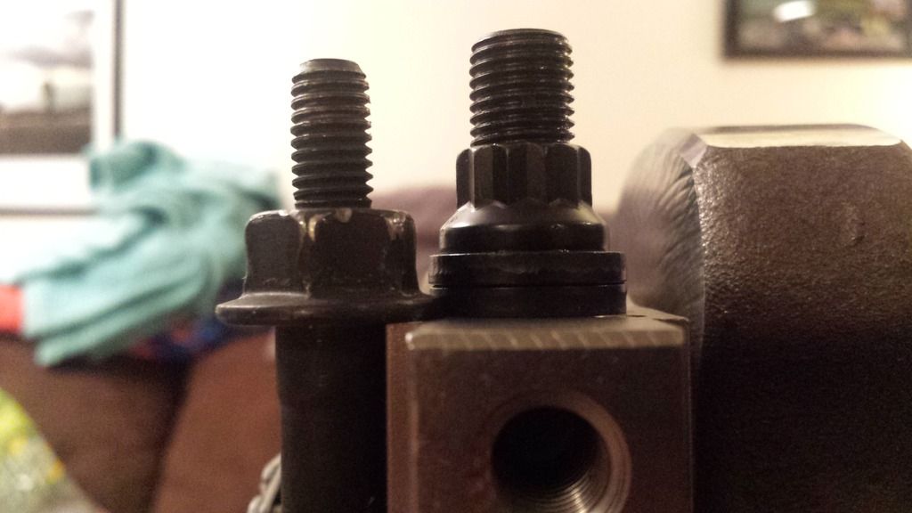
So has anyone actually tried the longer ARP main bolts with a windage tray? Because um, call me crazy but the pan wont fit now, it hits the tray.
The double washers under the bolts as well as the taller nut that the tray is sitting on raises its position at least .25" further away from the mains closer to the pan. The height of the double washers is .250 so I can only assume the nut is the same .400 height as the old bolts had, SO if there was enough thread on the studs to run with no washer and the nut had a collar built in it would probably be the same height but there is no way this will work without cutting up and bending the whole front section of the windage tray to clear the oil pan. I'm tempted to just run the factory hardware to avoid that headache.
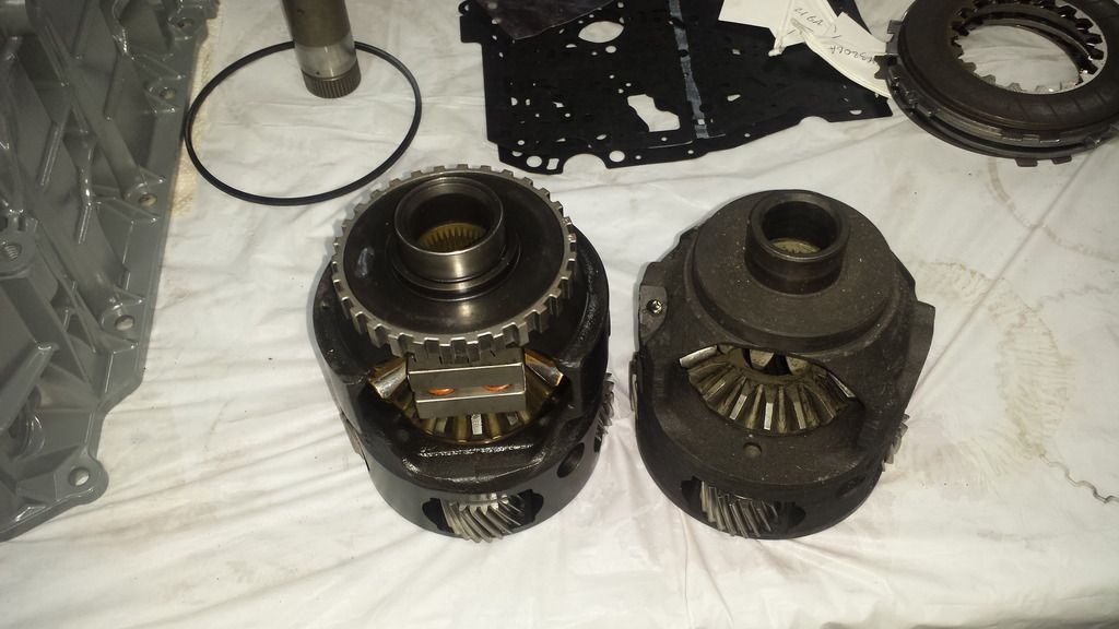
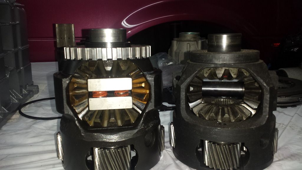
As many know I take apart everything to look it over... so here is the side by side comparison of the HD diff spiders and pin and the stock non HD stuff...
Got the new LSD 4t60e-HD... Slight upgrade in size
They LOOK similar from the top....
Not so much anymore.
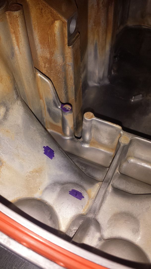
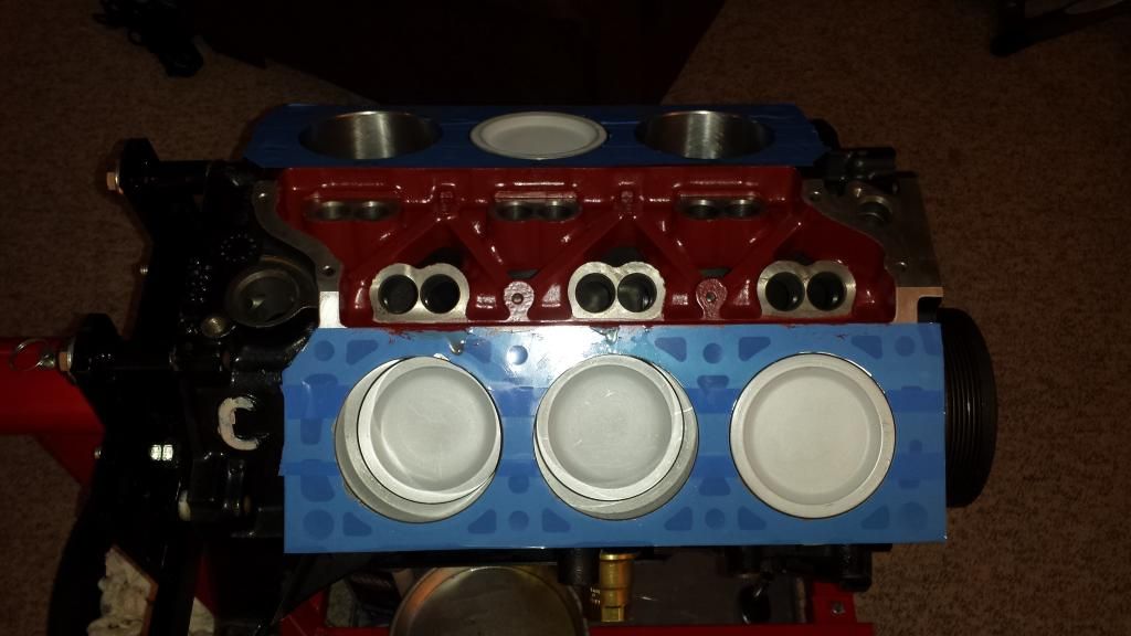
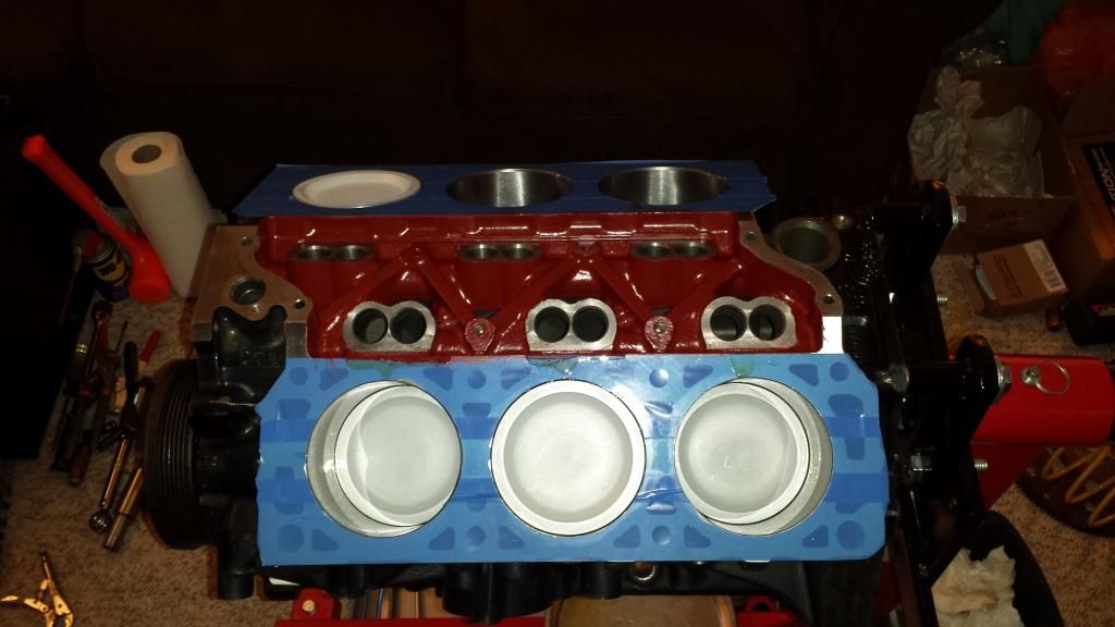
Should be getting the heads back soon... Also the DRTC hits on the two raised area's from the Front Main bolt holes... So I need to tape everything off to keep the shit out seeing how it's assembled, and clearance that area. Luckily I was able to clearance the galley plugs by just removing them and hitting a grinding wheel and re-installing them. I guess better I found it now and didn't take it apart to see some self clearancing going on.
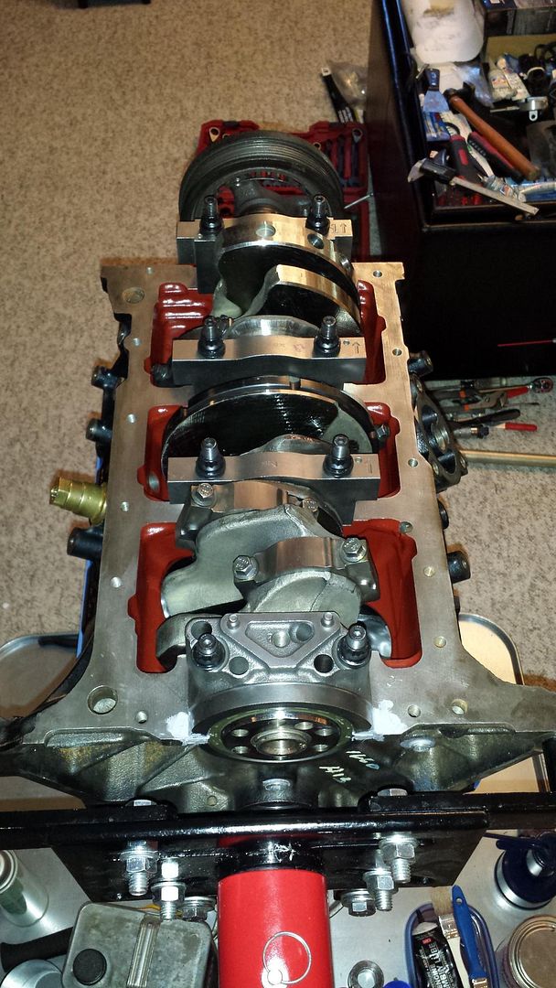
Got some more time to work on it last night... During rough assembly I noticed the main studs did not all sit at the same height so I had to get a M11x1.5 tap and clean up the threads on all of the main holes. Once I got that done and all cleaned up I was able to move on to more major assembly.
Got a rotating assembly now with the mains torqued down. Just need to torque all the rods and then get the windage tray and oil pump on... Then onto cam install and hopefully I'll have my heads by then so I can measure the pushrod length. Slow and steady... LOL
Also got conformation from Jeff at EP that he is shipping my LSD 4t60e-HD diff this Sat, So I'll have all the parts for that so I can start to figure out what else needs to change.
So I opened this can of worms in the chat box but explain these clearance issues to me....
3500 Specs pulled from 2005 Restore Manual... Same specs on this site as well.
Connecting Rod Bearing Clearance
0.18-0.062 mm
0.0007-0.017 in
This one is easy... Looks like they left out a Zero on the MAX piston production clearance spec
Piston to Bore Clearance - production
-0.029 to +0.029 mm
-0.0011 to +0.011 in
I'm wondering how many more tolerances are wrong...
3100 spec is .0007 to .0024 so I'm guessing they left a zero off the first mm spec and then totally f-ed up the conversion on the max of that. I wonder what a rod would sound like with 17 thou of clearance...
I guess it depends on how you interpret their surface prep directions... It says "Surface to be painted should be dry and free from dirt, wax, grease, rust and oil. Remove all grease and oil by washing surface with mineral spirits. Wipe or scrape off all loose dirt, rust or scales." Says nothing about grinding any area smooth... Most people de-burr area's to open up the drain holes as well as remove dams that are created from the casting process... I did that on the block already and then had it jet washed and honed and decked. All I did prior to this painting was spray and wipe down all the areas with Grease and Wax Remover paint prep.


Leave a comment: