-
Seeing how the nitrous is only used at the strip, I was actually contemplating installing a manual bypass valve so I can enable and disable that low pressure loop instead of the solenoid valves since in all honesty that system never has to be enabled remotely... I still have to turn the bottle on manually. -
One last thought after I sent my last response. I agree with your thoughts and should work fine. If by chance you do experience any problems associated with the low pressure bypass system, a pair solenoid valves installed could be used to isolate the low pressure system during normal operation. I doubt it will be needed though.Leave a comment:
-
Yes it does return to the pump chamber. IIRC it's just a outlet at the top of the pickup that pours down on top of the pickup assembly.
And in reality the stock bypass regulator (or aftermarket one I'll install) is working 100% of the time anyways... There is always fuel being returned to the tank to regulate the 48-55PSI it's set for so it's always bypassing something. They sell service kits for 22 bux.
I could buy two 13301's and use the low pressure spring included on one of them and the high on the other... Makes it simple and will look better if you ask me because they will match lol.Leave a comment:
-
I was offered two solutions by aeromotive... One was to install a stand alone fuel setup for the nitrous... Fix all but expensive... 599 is the cheapest I found and F-body specific. Next solution was to take the return from the injectors and feed that to another bypass regulator and create a 7-12 PSI back pressure on the first regulator. I asked him if this would affect the first regulators pressure at all, because if it doesn't then this may be the easiest and cheapest way to go.
Going to a pump system like you described really creates issues for my setup due to working with the stock tank, pickup and baffles right now... A free flowing siphon of 3/8 line will empty the pump chamber quicker than it can fill it up with the current way that tank is baffled... at least when it's got less than 1/2 tank in it... not sure how wll it works when it's full.Last edited by 3400-95-Modified; 12-17-2014, 12:54 PM.Leave a comment:
-
Have been following your project with great interest. The fuel system problem you are faced with is complex to say the least and trying to use the high pressure pump to supply both high and low pressure systems creates some complexities that are difficult to overcome. As you noted earlier, using a bypass to lower pressure for the low pressure side of the system can cause the whole system's pressure to drop to that level starving the injectors. You might think out of the box so to speak and look at the system in reverse. A high volume low pressure pump with available regulator can be set to the requirement of the low pressure system. Teeing off of that delivery system, a booster or high pressure pump can be installed to supply the needs of the high pressure system. Still some complexities but not nearly as difficult to overcome as what you are presently considering.Originally posted by 3400-95-Modified View PostLeave a comment:
-
Got some info back from Aeromotive... Can't run a static regulator with a inlet pressure of 55, they are only spec'd for something around 20 PSI. I'll have to find another way to do a second loop...
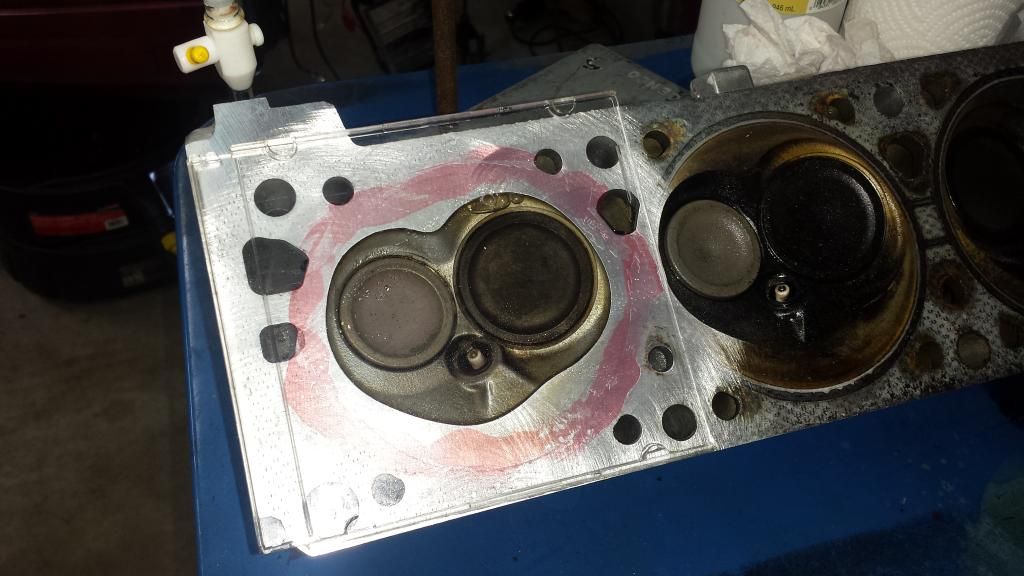
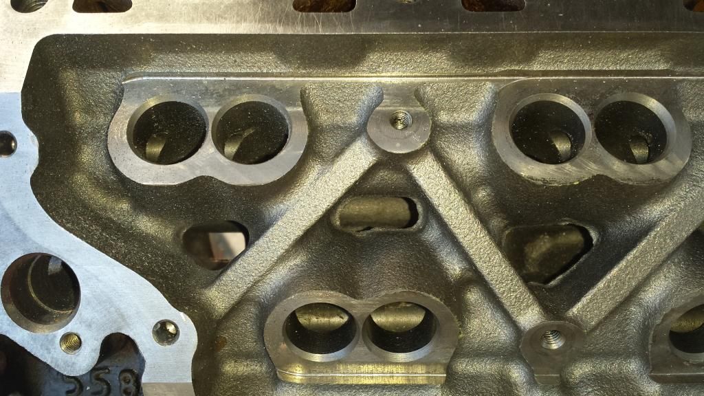
Did some head tear down last night... and CC'd the chambers. Came up with 32cc's... Original is 32.4 so not as much removed as I thought... May still have them shave just a bit to get them in the realm of 31.5 or 31cc's. Currently the setup I have picked will result in a 10.12:1 CR... Almost a full point over what I had in the past... around 9.2:1 using the same head CC's and the rest of the stock 3400 components. I gained over the 3500's 9.8:1 by going with thinner cometic head gaskets, .051 compressed vs .060 as well as the cometic gasket bore being 95mm or 3.74 vs stock 3.8". I may get the block decked .005 but I'm not sure yet.. that would put me at 10.26 but it brings the pistons and valves closer together... Not sure on clearance needed with whatever I end up with for a new cam.
CCing...
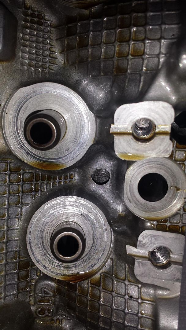
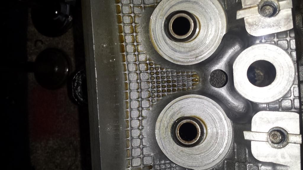
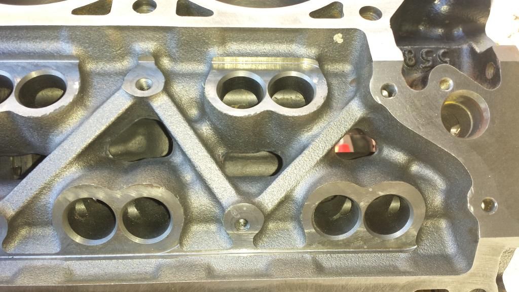
De-buring oil drain's on heads
Before
After
Leave a comment:
-
I then dug into the old motor today to look things over.
Front cam bearing was in fact extremely flush to the block which gave very little space for oil to flow out the thrust plate. Also this cam bearing set I never drilled the second hole in for the 1st bearing... Stupid me on that deal. Current chain was still in good shape, Not as tight as it was when I installed it but not loose enough to cause noise yet... And that was just a cheap Advance auto one I threw in last year sometime.
And now on to the bad news... But I think this will end well.
Time for a new cam.
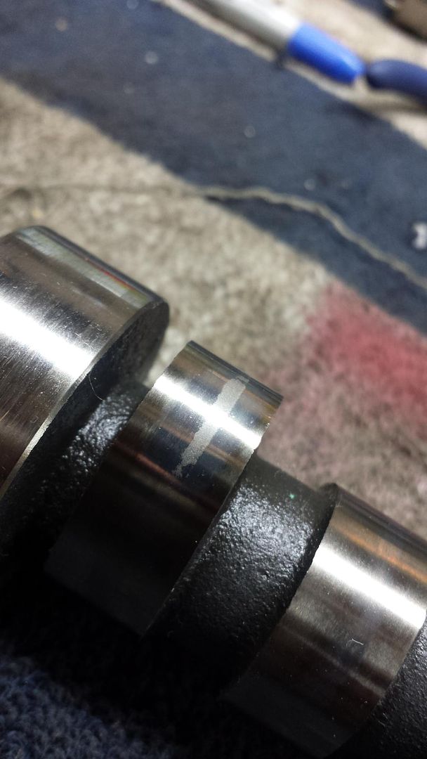
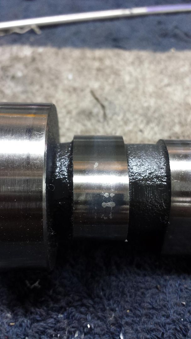
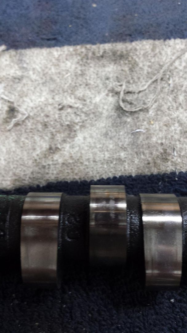
Three lobes have markings of the cam face starting to disintegrate... Was nervous when I started pulling the lifters and saw some funky markings on a few... This explains the marks.
Oh Ben.... Time to spec me up a custom cam... And pushrods... And if I HAVE to I'll swap springs
Leave a comment:
-
Well got some progress this weekend....
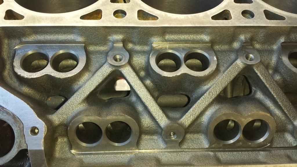
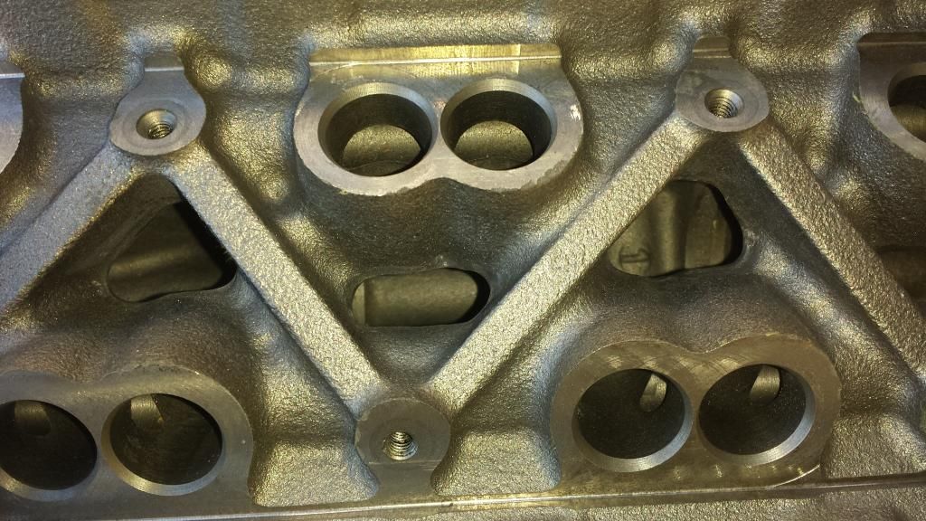
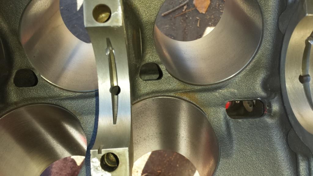
Removed all the casting flash from the block, Went really quick compared to what I though it was going to...
Before
One in progress
Lifter Valley
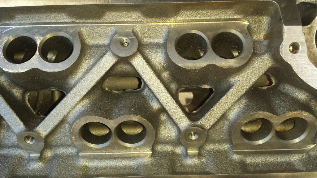
After
Leave a comment:
-
Well your's at least had the grooves on the back to allow oil out from the thrust plate... My original one and the whole second run were lacking those grooves... that's why it died in 5k miles for me... at least that's the assumption.
I'm just going a bit more overboard to hopefully assist in oiling.
Only person I know of that had issues with the first run was Bob442Last edited by 3400-95-Modified; 12-12-2014, 11:25 AM.Leave a comment:
-
Hmm......I wonder how long my unmodified DRTC (from the first run) will last?
I've got about 5000 miles on it now.Leave a comment:
-
On to other discussion...
After going back and forth with Marc last year about DR timing chain and oiling issues we came up with a few solutions to try and ensure that the chain gets sufficient oil.
One is modifying the cam bearing to have two holes in it since the aftermarket SBC bearings you get you don't use the #1 in the pack because its too large, you only use bearings 2-5 all of which only have ONE oiling hole in it. One replacement 3400 bearing that Marc found had the two holes on the front #1 bearing like the factory ones do, AS well as a groove cut in the 3 O'clock position hole to allow for oil to make it out to the thrust plate and timing chain assembly. I will be drilling the second hole in my cam bearing as well as making a slight groove to direct more oil out that way.
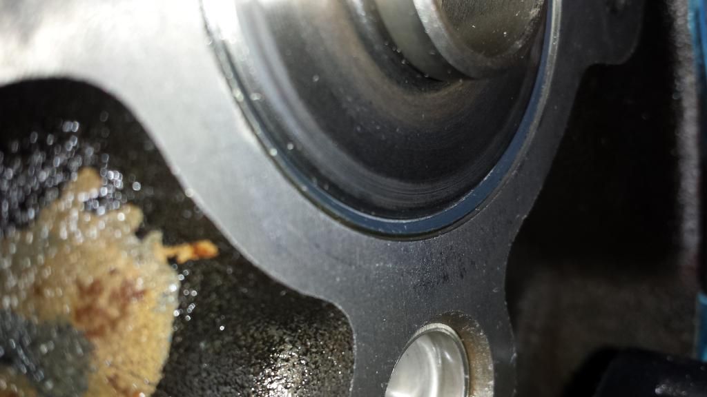
Then next thing is recessing the bearing into the block as it's done by the factory to allow clearance between the bearing and the thrust plate seeing how the holes on that don't always line up very well with the cam/bearing gap.
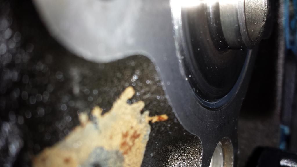
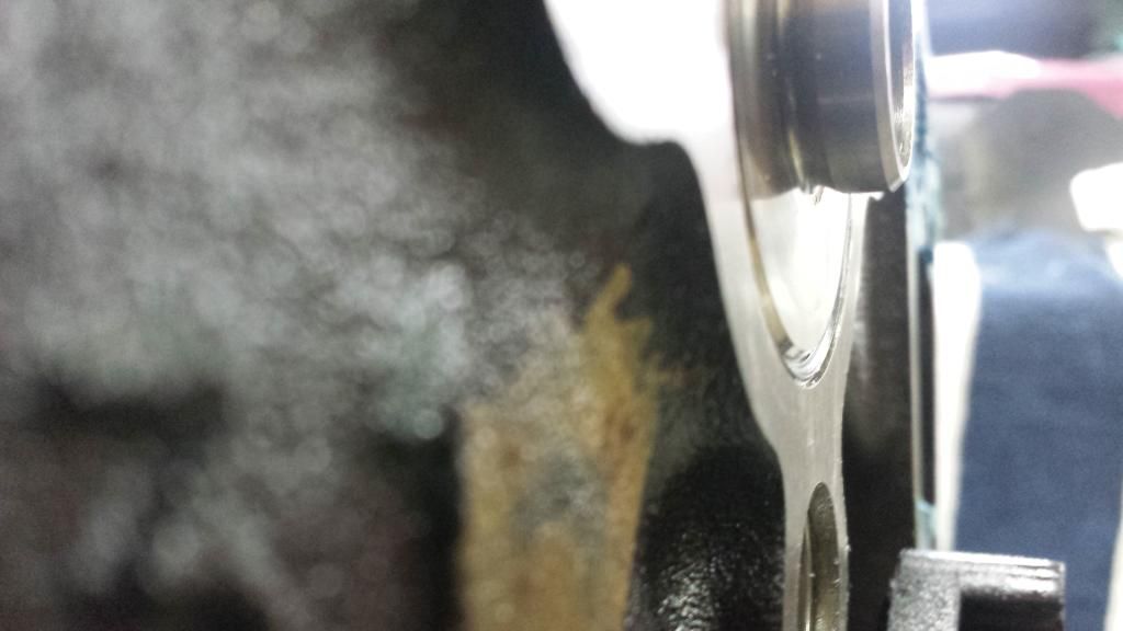
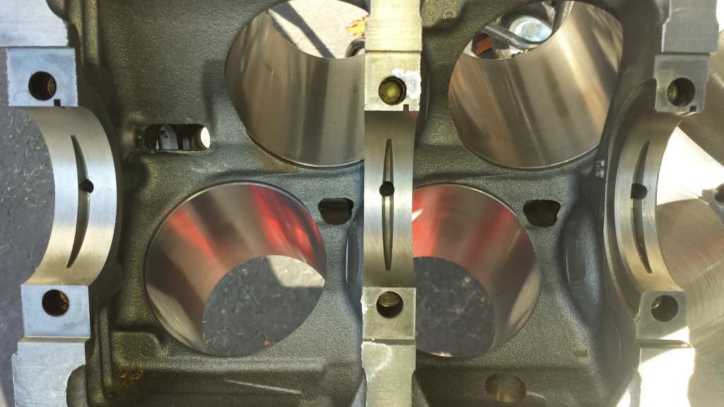
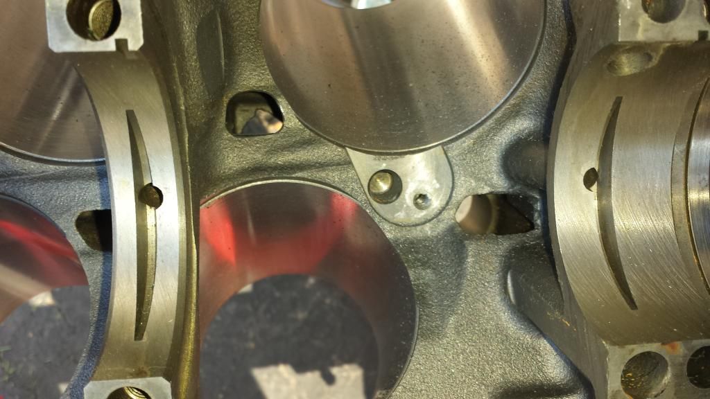
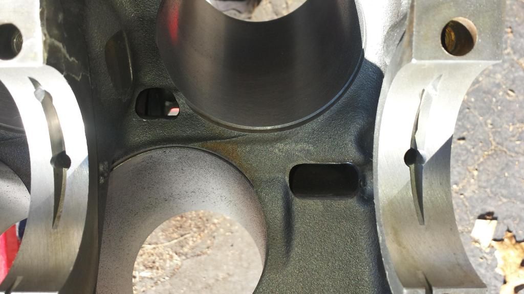
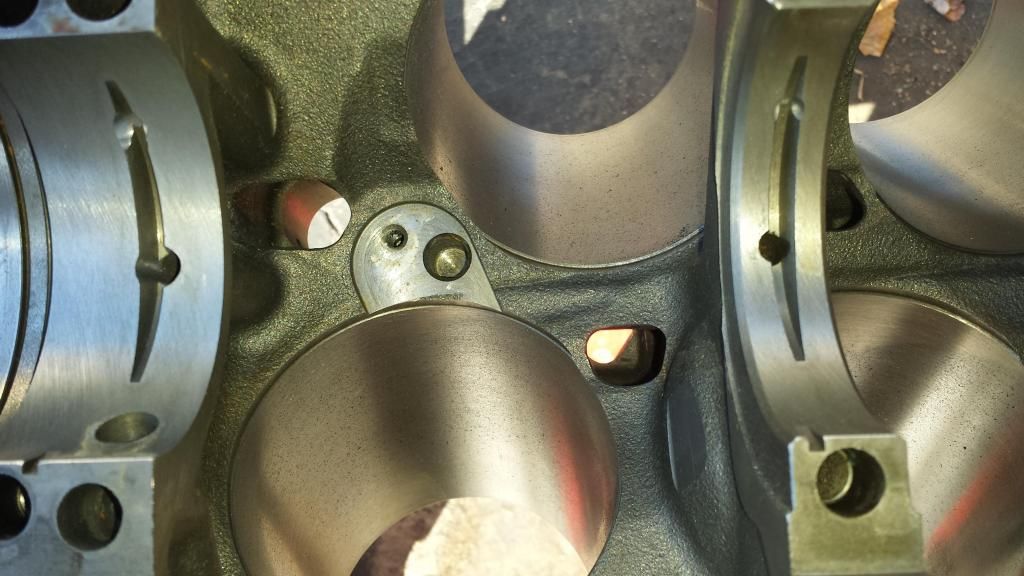
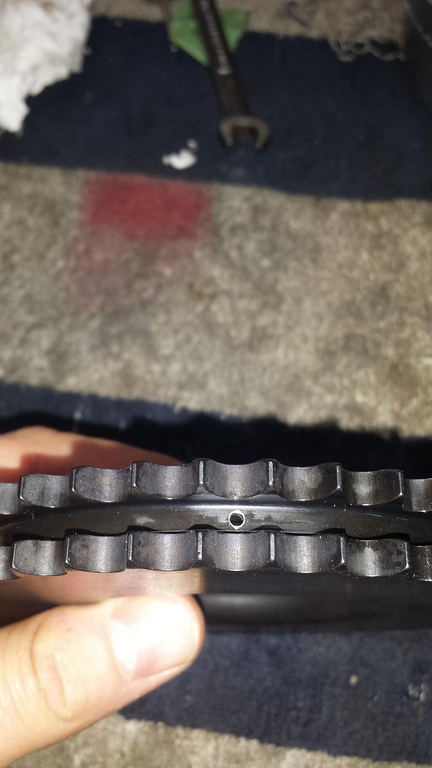
You can see the recessed bearing compared to the block face here.
It's hard to see in this photo, but the gap between the cam and bearing is not centered in the holes for the thrust plate... They drilled those holes I believe on the same diameter as the block cam journal, and not the actual journal size on the cam itself.
You can see how the oil stains are pretty well cut in half in relation to the block cam bore ID and not the bearing ID.
You can see in this diagram Marc drew the diameter of the bearing ID in relation to the plate, then a cross section of the sprocket, plate bearing and cam with the bearing flush mount, then recessed and then finally recessed with oiling holes drilled into the cam sprocket.
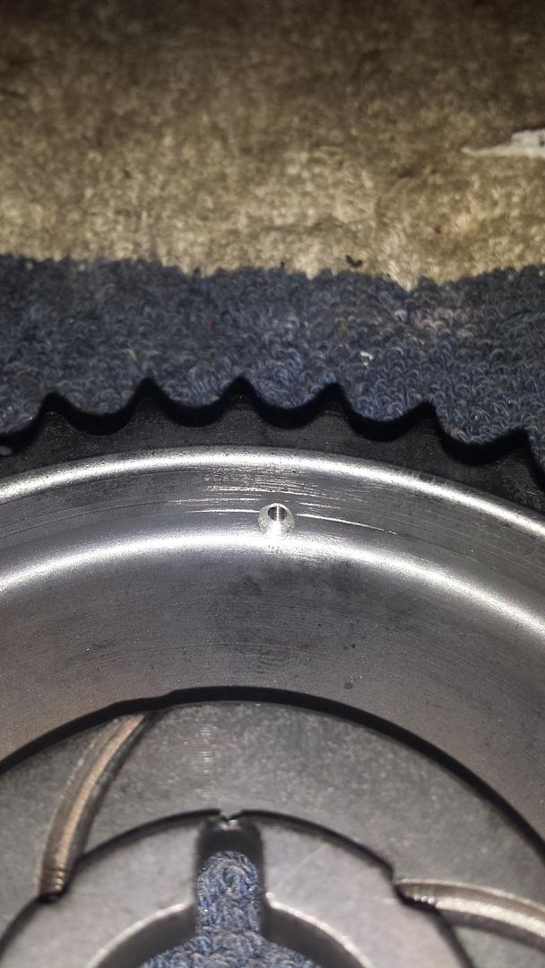
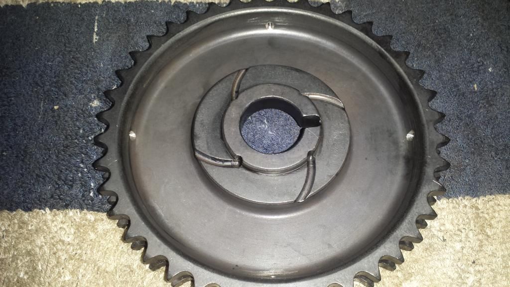
I will be doing the last cross section because I also drilled 4 holes in the DR upper sprocket.. I mean it can't hurt to direct the oil to the center of the chain rather than the backside only.
Hopefully all of this will result in a long lasting chain...Leave a comment:
-
Well I plan on using Aeromotive regulators so I contacted them a few days ago regarding this and still haven't received a response.Leave a comment:
-
Without knowing your fuel pump's curve or the regulator's specifications, you will only be able to make a guess. If it were me, I would pose that question to Holley. Contact their technical service @ Technical Service: 1-866-464-6553 or www.holley.comOriginally posted by 3400-95-Modified View PostLeave a comment:
-
You could probably purge the returnless line back into the regular return lineLeave a comment:
Leave a comment: