Announcement

Collapse
No announcement yet.

Exhaust Collector Discussion

Collapse
X
 
  • Filter
  • Time
  • Show
Clear All
new posts

  • TGP37
    replied
    Originally posted by slw240sx View Post
    why are you knecking down the collector then bringing it back to a full sized pipe diameter? At least it looks that way. I know on NA applications this is done to produce an effect, but on a turbo app this will actually hurt gas velocity as it enters the turbo. you want to come out of the collectors into either smaller piping or same size piping as the outlet at the collector. enlarging it i would think would have a negative effect on velocity.
    Thank you, this is exactly why I post here. I have a lot to learn yet, but I am on my way.

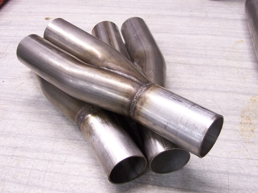
    I am taking your advise and removing the taper. I thought it was for velocity but didn't realize the difference in turbo apps. Speaking of the collector, I still yet have to find the idea diameter for the primaries. Also need to figure the cross-sectional ratio from 3 smaller pipes to one larger pipe. Should I maintain equal cross section area?

    Example,

    Using 16 gauge as the example (roughly 0.0625" or 1/16" thick)
    Primaries, 1.75" OD / 1.7375" ID
    Surface Area of Circle = 2.37"²
    Three Primaries Total = 7.11"²

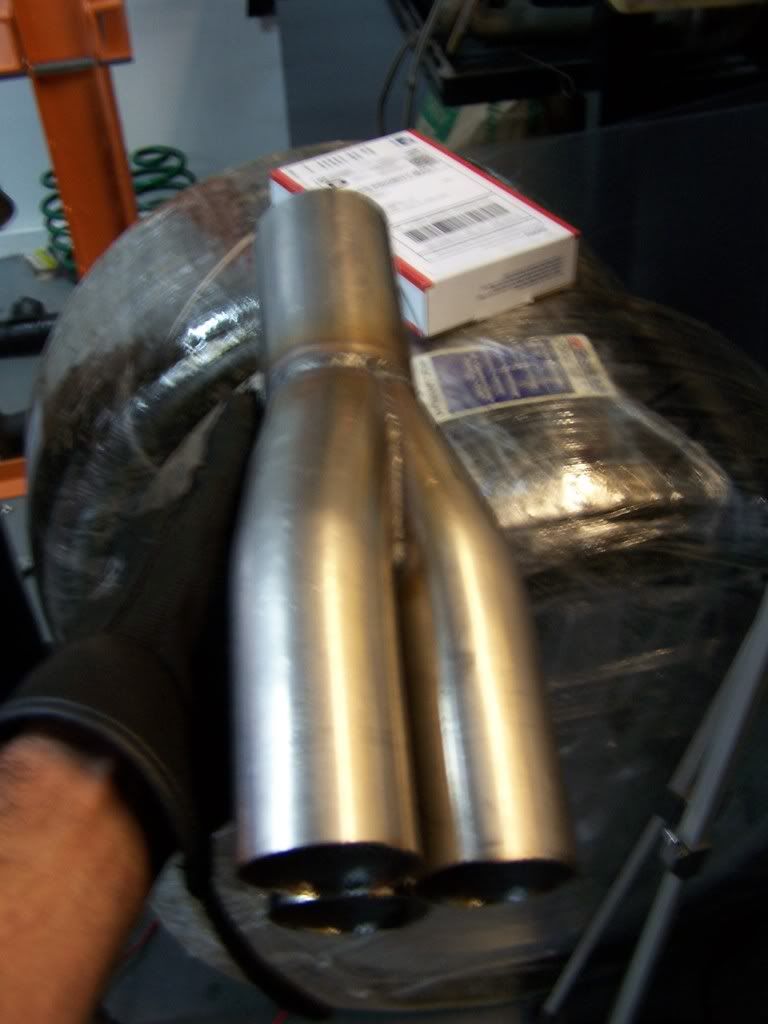
    Secondary Pipe Diameter = 3" (which is A= 7.11"²)

    But if I go 1.5" Primaries then the secondary should be (1.767"² * 3 = 5.3"²) diameter of 2.6" ID , 2.725" OD.

    But it seems excessive to have two 3" pipes merging into the Turbo. But that is how the math states it.

    Any advise there?

    EDIT UPDATE: I think I am missing pressure as a factor and that all 3 exhaust primaries aren't flowing at once. So I think I should approach the equation with mass instead of volume. And then knowing the average ambient pressure in the header primary while valve closed and when there is flow. So then the secondary pipe should flow (2x ambient PSI + 1x boosted exhaust PSI ) = secondary diameter to maintain steady velocity for a given PSI during 1 primary flowing. Ugh, thats gonna be a cruncher. I need to read up on my physics books I have lying around.

    Originally posted by pocket-rocket View Post
    It's called scavenging. Drawing the exhaust out faster than it would normally flow out to help evacuate the cylinder, sort of like removing the EGR. It also somewhat produces a vacuum when valve overlap occurs.

    Header designs on NA builds are very important.
    Here is the big question, Why do people say the header won't work the same on a turbo?

    I know it seems like a silly question but if the scavenging effect is created at the collector, then in theory exhaust under pressure would still create a lesser pressure reversion wave which would aid the excavation of exhaust gases under greater pressures and heat. Same mechanics just at a higher pressure with greater heat. But what of the turbines effect on all of that?
    Last edited by TGP37; 08-16-2011, 10:08 PM.

    Leave a comment:


  • pocket-rocket
    replied
    Originally posted by slw240sx View Post
    NA and nitrous you are working with uncompressed intake charges and you are using the motor to move the air and the exhaust system as part of the "pump" to keep it moving. i have read up on the theory, but it is in one ear out the other because i refuse to spend time building NA setups when for the same amount of money we can normally double the output with a simple forced induction setup.
    It's called scavenging. Drawing the exhaust out faster than it would normally flow out to help evacuate the cylinder, sort of like removing the EGR. It also somewhat produces a vacuum when valve overlap occurs.

    Here's what wiki says about it:

    Originally posted by Wiki
    When an engine starts its exhaust stroke, the piston moves up the cylinder bore, decreasing the total chamber volume. When the exhaust valve opens, the high pressure exhaust gas escapes into the exhaust manifold or header, creating an exhaust pulse comprising three main parts: The high-pressure head is created by the large pressure difference between the exhaust in the combustion chamber and the atmospheric pressure outside of the exhaust system. As the exhaust gases equalize between the combustion chamber and the atmosphere, the difference in pressure decreases and the exhaust velocity decreases. This forms the medium-pressure body component of the exhaust pulse. The remaining exhaust gas forms the low-pressure tail component. This tail component may initially match ambient atmospheric pressure, but the momentum of the high- and medium- pressure components reduces the pressure in the combustion chamber to a lower-than-atmospheric level. This relatively low pressure helps to extract all the combustion products from the cylinder and induct the intake charge during the overlap period when both intake and exhaust valves are partially open. The effect is known as scavenging. Length, cross-sectional area, and shaping of the exhaust ports and pipeworks influences the degree of scavenging effect, and the engine speed range over which scavenging occurs.

    The magnitude of the exhaust scavenging effect is a direct function of the velocity of the high and medium pressure components of the exhaust pulse. Performance headers work to increase the exhaust velocity as much as possible. One technique is tuned-length primary tubes. This technique attempts to time the occurrence of each exhaust pulse, to occur one after the other in succession while still in the exhaust system. The lower pressure tail of an exhaust pulse then serves to create a greater pressure difference between the high pressure head of the next exhaust pulse, thus increasing the velocity of that exhaust pulse. In V6 and V8 engines where there is more than one exhaust bank, Y-pipes and X-pipes work on the same principle of using the low pressure component of an exhaust pulse to increase the velocity of the next exhaust pulse.

    Great care must be used when selecting the length and diameter of the primary tubes. Tubes that are too large will cause the exhaust gas to expand and slow down, decreasing the scavenging effect. Tubes that are too small will create exhaust flow resistance which the engine must work to expel the exhaust gas from the chamber, reducing power and leaving exhaust in the chamber to dilute the incoming intake charge. Since engines produce more exhaust gas at higher speeds, the header(s) are tuned to a particular engine speed range according to the intended application. Typically, wide primary tubes offer the best gains in power and torque at higher engine speeds, while narrow tubes offer the best gains at lower speeds.

    Many headers are also resonance tuned, to utilize the low-pressure reflected wave rarefaction pulse which can help scavenging the combustion chamber during valve overlap. This pulse is created in all exhaust systems each time a change in density occurs, such as when exhaust merges into the collector. For clarification, the rarefaction pulse is the technical term for the same process that was described above in the "head, body, tail" description. By tuning the length of the primary tubes, usually by means of resonance tuning, the rarefaction pulse can be timed to coincide with the exact moment valve overlap occurs. Typically, long primary tubes resonate at a lower engine speed than short primary tubes.


    Header designs on NA builds are very important.

    Leave a comment:


  • slw240sx
    replied
    Originally posted by ForcedFirebird View Post
    I agree with the FNG (yeah you Jon, lol). You don't need to get so elaborate with turbo collectors beyond a nice merge. In N/A applications it is more important, but making collectors like the ones below are difficult enough to make, nevermind "vortex collectors"...


    I don't like using thin walled pipe for turbo applications, they always crack unless you have extreme turbo bracing since the heat cycles will practically melt - used 14ga on a couple applications and they held with extra welding and bracing, but the sch10 will hold the weight, heat and is actually easier to weld.

    I also used that Honda forum to get ideas to make a jig to produce the above collectors, but had to change things a bit since I was using 18degree bends for a Burns-style collector rather than sch10 straight piping. The 2-1's were made on the bandsaw, the 3-1 was made on a metal cutoff saw.

    I will disagree, though, that collector design doesn't matter. In N/A, S/C and nitrous applications, it is VERY important. A local here with an outlaw Buick Regal (7second car) picked up several tenths by switching to a Burns collector and larger primaries.
    i completely agree in NA sc and nitrous apps that collector design is important. the reason is because you are using the exhaust gases in a different means. in a SC i would think its a little less important as bigger is probably better just to get the pressure out faster. NA and nitrous you are working with uncompressed intake charges and you are using the motor to move the air and the exhaust system as part of the "pump" to keep it moving. i have read up on the theory, but it is in one ear out the other because i refuse to spend time building NA setups when for the same amount of money we can normally double the output with a simple forced induction setup.

    Leave a comment:


  • slw240sx
    replied
    Originally posted by TGP37 View Post
    I decided to try a different, less intensive approach. And it just so happened to be just like the pics ForcedFirebird posted.

    And it will be easier to pipe together since the 3 inlets are lined up side by side.

    [ATTACH=CONFIG]6056[/ATTACH]

    My theory, atm, is to take a tried and true method described above. Then attempt to achieve perfection in measurements, cuts, blending, polishing, etc.

    The nice part about this style is the ease of cutting. It is a straight line cut from above.


    I heard once the header is ineffective with turbochargers. Is this true? It seems the impulse from the opening valve should still create a reversion wave at the collector regardless if there is a turbine down stream or not. Unless I am wrong....
    why are you knecking down the collector then bringing it back to a full sized pipe diameter? At least it looks that way. I know on NA applications this is done to produce an effect, but on a turbo app this will actually hurt gas velocity as it enters the turbo. you want to come out of the collectors into either smaller piping or same size piping as the outlet at the collector. enlarging it i would think would have a negative effect on velocity.

    Leave a comment:


  • TGP37
    replied
    I decided to try a different, less intensive approach. And it just so happened to be just like the pics ForcedFirebird posted.

    And it will be easier to pipe together since the 3 inlets are lined up side by side.

    Click image for larger version

Name:	v6 collector reverse merge.jpg
Views:	1
Size:	103.0 KB
ID:	376813

    My theory, atm, is to take a tried and true method described above. Then attempt to achieve perfection in measurements, cuts, blending, polishing, etc.

    The nice part about this style is the ease of cutting. It is a straight line cut from above.


    I heard once the header is ineffective with turbochargers. Is this true? It seems the impulse from the opening valve should still create a reversion wave at the collector regardless if there is a turbine down stream or not. Unless I am wrong....
    Last edited by TGP37; 08-16-2011, 05:08 PM.

    Leave a comment:


  • ForcedFirebird
    replied
    I agree with the FNG (yeah you Jon, lol). You don't need to get so elaborate with turbo collectors beyond a nice merge. In N/A applications it is more important, but making collectors like the ones below are difficult enough to make, nevermind "vortex collectors"...


    I don't like using thin walled pipe for turbo applications, they always crack unless you have extreme turbo bracing since the heat cycles will practically melt - used 14ga on a couple applications and they held with extra welding and bracing, but the sch10 will hold the weight, heat and is actually easier to weld.

    I also used that Honda forum to get ideas to make a jig to produce the above collectors, but had to change things a bit since I was using 18degree bends for a Burns-style collector rather than sch10 straight piping. The 2-1's were made on the bandsaw, the 3-1 was made on a metal cutoff saw.

    I will disagree, though, that collector design doesn't matter. In N/A, S/C and nitrous applications, it is VERY important. A local here with an outlaw Buick Regal (7second car) picked up several tenths by switching to a Burns collector and larger primaries.

    Leave a comment:


  • SappySE107
    replied
    Originally posted by slw240sx View Post
    I know you guys will probably not take a word i say as legitimate as the bias here against people from our side of the coin seems rather high.
    bias through experience. Ill take it.

    Leave a comment:


  • TGP37
    replied
    hey Jon, I now realize your advise has more weight then previously thought. Unfortunately my first impression of you was stained by the "Dave" drama. But I know better then to judge another by such little understanding who they are.

    In light of that, I'm sorry if I came of with the "Better then thou" attitude.

    Now, this turbo project is more of a personal mission then just making a turbo. I aim to perfect a lot more then most would consider, even though I am a novice. Like Sappy said recently, some things are just dreams, but other things are potential points to squeeze a little more efficiency, performance, etc. Besides the time spent, I do firmly believe refining a header collector (with respects to the entire build) will provide less turbulence in the center where all 3 primaries meet up.

    I have not made a final choice of material to use or the gauge. But you mentioned Sch10 Stainless Steel?

    This design I am working on is the 3rd round of manifold design for the turbo. The 1st was just the cross over cut open with 10 gauge steel plates welded to a box, to the turbo flange. It worked but was obviously restrictive as the two sides impacted each other head on.

    The second design, which is the current one, has A LOT of thought to geometry and flow. But still, it is based off the stock log manifolds. And I feel I can do a little better. So for now the current one stays on while I take the time to design a superior cross-over turbo manifold.

    CAD designs are great for initial layouts. Once I set the boundaries where I can place the primaries/collector, I can design it and find a way to make all 3 primaries equal length with as little as bends as possible.

    Any advise you wish to provide is 100% welcomed. Sorry about the book comment, like I said earlier, I associated you with Dave. But I take that back now.

    Leave a comment:


  • bszopi
    replied
    Jon,

    I would also like to welcome you, and thank you for joining the forum. I follow your posts over on GAGT.com, but unfortunately can no longer post over there. But anyways, I fully agree with everything you have said, and just to note, Ben and I often link people to a Honda (primarily) resource for the excellent information on general engine dynamics: http://theoldone.com/ Being in the world you are in, I would hope you have heard of Endyn and Larry Widmer.

    Leave a comment:


  • pocket-rocket
    replied
    Originally posted by slw240sx View Post
    ......


    Jon @ ForcedFab
    Not to thread jack, but...

    You seem to be an extremely down to earth guy, I respect that. Had Dave come in here with the same attitude you presented yourself with I'm sure many more would have taken him more seriously.

    Thanks for the links, I'm going to give them a look over as I'm always looking for information to make my knowledge more broad in the world of modifying cars. I know most guys here are open minded enough to read over Honda forums, as most here aren't that closed minded like some of the back woods "nothing can beat my V8" kind of guys.

    Leave a comment:


  • TGP37
    replied
    Originally posted by Superdave View Post
    I made some true merge 3:1's for my current longtubes, had to use paper templates and an air nibbler to cut the tubing right. then a die grinder with a carbide cutter to clean up the seams on the inside. A Plasma cutter would be VERY nice for this...

    It was a royal pain in the ass but i guarantee they are better than the cheepie 3:1's i was using before.
    What kind of gains did you see? Or is that an unknown?

    I do believe they are better, just how much better is the question I think about. I have a paper mache' like replica of the mandrel bend. Made them w/ glue soaked paper strips and let dry. They turned out really well. But I plan to mark a grid over the temps to match the wireframe on the virtual design. Transposing the curve lines wont be hard, just time consuming. But I'll have a set of templates to use over and over again. So the next 5 cut pieces will be easy.......hopefully.

    Leave a comment:


  • TGP37
    replied
    Originally posted by slw240sx View Post

    ...

    Jon @ ForcedFab
    omg, you posted a book, lol.

    There is nothing wrong with exploring an idea. The twisting part is more a curious intention, the real part of the collector is merging smoothly. I am a beginner with turbo building BUT, I can not let go of a common knowledge of physics.....a better merge will make better flow.

    2 flex joints pre-turbo, and they are just before the merging of the cross-over. the other is before the test cat.

    It seems you think I am building a high boost car. I agree with most of what you posted, but is over kill for a 5-8 psi turbo. I dont even consider hitting 15 psi, though it was built in mind to hit that high.

    I just can not tack 3 or 4 pieces of pipe together and call it half a collector. Sure, its fine to use and works but, I am a diy builder (not just turbos) and if I can do better, I will. And even though the welds are really ugly, they are strong as ever. I dont weld for looks, I weld for a molten bond between steel and welding material. I tack weld but each weld is literally melted into the pipe, not just steel glued. It is messy but I could weld two 4' pipes together and stand on the seam w/ ends on a brick or something.

    Ahh its okay dude, I will be fine. What is over thought for others is daily day dreaming for me. Thanks for the links

    Originally posted by SappySE107 View Post
    Nope, it won't stay geometric even if you used a straight piece of tubing. Since it isn't steady flow, it is going to roll and tumble its way around inside the tube. It was probably on speedtalk that I saw the pictures of how the flow worked it way through the tubes, but I don't recall how they even had the pics. Ah, the novelty of forgetting details What I gained the most was to forget about making any real sense of it without testing. The varying lift of the exhaust and the cam timing will be a part of this (and imagine variable cam timing, woohoo!).
    I understand now, I was caught in a visual error. More like water rushing down a curving water slide?

    I know one thing, that flow is anything but linear after squeezing threw the valves...lol

    Originally posted by pocket-rocket View Post
    Spatter spray and preheating the tubing with either propane or MAPP could have helped. Better late than never, and yes, function over appearance. I think that's the definition of fugly. Fast + UGLY= FUGLY
    Fugly, haha. We used that in High School for the "FAT" and Ugly. A friend may have nailed an ugly chick, we just shake our heads and tease them. But a real friend won't let friends tag a fugly chick...no matter how wasted.

    I considered making copper shield with magnets attached, the right diameter for the pipe being welded. Just set them in place and go. But then, spatter never really bothered me much and has been great holding the wrap in place. If I was welding a piece that is in view, I would then take steps to reduce spatter.
    Last edited by TGP37; 08-16-2011, 07:43 AM.

    Leave a comment:


  • slw240sx
    replied
    I know you guys will probably not take a word i say as legitimate as the bias here against people from our side of the coin seems rather high. I can not speak on daves attitude as he says and does what he wants most of the time. Even to the point where i have fired him in the past because of negative behavior and the outlook it had upon my shop. I have rehired him before and he works for me part time when i need help around the shop. He has a wealth of knowledge, unfortunately his immature attitude often discredits his knowledge.

    This is about giving you guys good information though. I am not here to bash on anyone, just to offer up my advice and constructive criticism. I come from a turbo building background, i have owned a shop for the past 5 years and we have built more cars then i care to remember almost every one being turbo. In all my years what i have learned most is that people often over think 90% of what they are trying to do. i have sat and read this thread and the porting thread and i have come to the conclusion that you are all just over complicating this issue when it comes to building a turbo kit. You do not need these fancy collectors you are trying to build. a simple press / stamped collector will work just fine for any HP level you intend to hit. I have used pressed style collectors on 700-800hp cars they were 4-1 collectors on v8 motors, but they work well. the 3-1 collectors will easily get you into 500hp range no problem they are not going to hold you back from making the power. the twist merge collector is just to time consuming to even worry about. yah its cool to cad things out and try them, but when it comes down to it. The time invested vs gain over normal collectors will be not worth it. i am not against building a merge collector over using pressed collectors. I am against it on a production kit that uses 16-14 gauge mild pipe due to costs. If i were building this out of schedule 10 304 SS weld L's i would spend the time to build a proper merge collector.

    I have spent countless nights looking over collector designs, collector fixtures, and welding techniques for them. I have found one really great wealth of information that i will pass on to you guys. Keep an open mind. the link i am giving is for a Honda forum. This honda forum though is more then just about hondas, they have a section dedicated to fabrication. The leading people in the sport compact and fabrication industry regular this forum and the amount of information and displays of work is amazing. I go here often for inspiration and to keep up on what is happening and to soak up new things. here is actually a really good "how to" guide on building merge collectors. These collectors actually use the stainless steel schedule 10 material i was speaking on earlier, but the techniques can be used on thinner materials. http://honda-tech.com/showthread.php?t=2787713
    the link to the welding and fabrication subforums http://honda-tech.com/forumdisplay.php?f=53

    You said you have 3 flex joints in the system? that alone will cause a nasty flow disruption that even the perfect merge collector would have trouble correcting. I personally try to avoid flex joints anywhere pre turbo as they do not hold up to the extreme heat very well, nor do they flow very good with most having a internal bellows instead of a smooth surface. Also the heat wrap while helping to keep the exhaust gas velocity up will actually do more damage to the pipes faster causing severe metal fatigue quickly leading to failure of the material. I had a customer that we built a set of turbo headers for a ford 302 and they were ceramic coated, but he heat wrapped them. the wrap held in a good amount of heat which over heated the coating resulting in a failure of the coating, and then led to a failure of the material around the collectors from where the heat concentrated. The collectors actually ruptured and came apart. This kit was only a few months old and it looked like an old burn barrel. the coaters refused to warranty the coating and i had to refuse to warranty the headers because he was warned ahead of time. I try to avoid the stuff at all cost when its near the heads. I can see doing the parts of the exhaust as it passes under the car because the heat there is less extreme, but it will help keep heat out of the cabin.

    I know you are doing what you can with a flux core, and i admire your DIY attitude! if i did not have the same DIY ethic i wouldnt have ended up with a turbo shop! I do though offer a suggestion on building the stuff. I see that you have a higher understanding of all this, but lack the finer skills to execute them. dont take that the wrong way its not a dig at you, it takes years to learn how to do this stuff and make it pretty and reliable. I have a good number of customers in a similar situation, they have the basic understanding of how to fab, they do not want to pay a shop to build their cars, but they want a good part. So what i offer to them is for them to build what they want. they are always welcome in the shop to ask questions, get pointers, and to bounce ideas off me. Most take me up on that and what we work out is that they will get together what they are building and tack weld or mark out parts for welding then bring it all over to me for final welding that way their parts come out looking for the most part professional. you cant always get the finished look of a pro due to their beginner skill, but it looks way better then what it would have had they done it all themselves. They get their parts on the cheap and i get to help them out in turn they keep the word about us moving around. i would suggest hitting up a local fab guy whether it be a speed shop like us or even a local weld shop with that 50-60 year old redneck as long as they have a tig welder they can probably get you going! keep up the work and keep posting pictures!

    Jon @ ForcedFab

    Leave a comment:


  • pocket-rocket
    replied
    Originally posted by TGP37 View Post
    I know it looks sloppy but that is the best I can get with this flux core welder.
    Spatter spray and preheating the tubing with either propane or MAPP could have helped. Better late than never, and yes, function over appearance. I think that's the definition of fugly. Fast + UGLY= FUGLY

    Leave a comment:


  • SappySE107
    replied
    Nope, it won't stay geometric even if you used a straight piece of tubing. Since it isn't steady flow, it is going to roll and tumble its way around inside the tube. It was probably on speedtalk that I saw the pictures of how the flow worked it way through the tubes, but I don't recall how they even had the pics. Ah, the novelty of forgetting details What I gained the most was to forget about making any real sense of it without testing. The varying lift of the exhaust and the cam timing will be a part of this (and imagine variable cam timing, woohoo!).

    Leave a comment:

Working...
X