 Tweet
Tweet
With ethanol blends, water contamination is only going to get worse. Refiners have had headaches trying to keep the ethanol pure when it's such a good solvent and wants to contaminate itself by cleaning up the transmission pipes, destroying valve seals, etc.
-
-
Along those lines, watch out what you use to clean parts before welding. I'd imagine some of you have seen this article but this is the kind of amateur mistake somebody like me could doOriginally posted by 60dgrzbelow0 View Post
http://www.brewracingframes.com/id75.htm
Glad you're making progress on the apparatus again.Comment
-
You're absolutely right. But isn't is funny that even with all that stainless steel being used in most of the other fuel system components, this "Morton Thiokol"-like FPR design always leads to a serious failure in the end? For example... the tragic and entirely avoidable $25 Billion Challenger Disaster as the unintended consequence of NOT including the Three Laws of Thermodynamics in their "Oh Sh*t" "O" Ring design considerations. Jesus Palomino!!! In this case though, the GM engineers either failed to test their ENTIRE system long enough under exposure to the natural elements (and sometimes unnatural ones) to discover the unintended consequences nature can throw at us, what with Hurricane Katrina-like events... and then the salt and brackish water flooding our vehicles, etc. ...or...there is always the convenient possibility they allowed the sub-component manufacturers to slip one over on them as to the alleged durability of Cadmium Anodized Steel Components in mixed metal<> mixed chemical fuel delivery environments.Originally posted by Tbay99Venture View Post
I thought about one other unusual circumstance that often rears its ugly head in nature when the ever-present chaos invades an otherwise fairly predictable dynamic fluid system. The weird cup design they decided upon using here and the concentration of the corrosion and damage in that location reminded me of what happens when a fast moving river stream encounters a linear obstruction. Any heavier sediment moving along or being pushed or carried within the stream will slow down and drop those objects as the water velocity on either one side of the river bank or the other continues along to maintain the volume of water while the fluid pressure adjusts here and there to get around these new obstructions. The velocity of the inner portion slows down while the out areas speed up to ensure that the same volume of water is getting through. In time, such rivers and streams will begin to "Ox-Bow"; meandering or oscillating from river bank side to the other as the heavier materials settle and collect over time, changing their directions, courses and shapes.
The stainless steel cup in this configuration strikes me as a perfect place for the heavier water to separate out from the fuel in the fast moving, pressurized stream by centrifugal force, leaving the water to collect inside the cup in the upper and outer areas where it can act to erode the Cadmium coating off of the inner race of the FPR. A similar action occurs in the swirling motion (caused by the Coriolis Effect) when flushing a toilet. Invariably any "rings" or deposits happen along the upper and out edges of the water bowl, in part because of this action. You don't have to look very far in nature to find the most striking empirical example of this happening. Just take a close look at the linked video showing the action of The Great Spot south of the equatorial plane on the planet Jupiter. Here is a perfect demonstration of how this phenomena works, even in such a gigantic, roiling and moving fluid system. You can see that even with all that gaseous mix in crazy motion, areas of calm can persist like this spot for hundreds of years.
In any case, as far as this dynamic fluid system is concerned, had they made ALL of these components out of stainless steel and not with any planned obsolescence in mind, the presence of this event would have made no difference in the overall performance of the fuel delivery-fuel injection system. Have a look at these examples as a visual point of reference that the S/S Cup design of this Vortec Rail is reminiscent in its basic shape to this bizarre event:
And in the case of the Ox-Bow phenomenon:
Last edited by 60dgrzbelow0; 12-09-2011, 11:31 AM.Comment
-
Hello Folks...
For the "Visual Shorthand" of the latest efforts... Please go here if other things in your Friday evening hold sway with your attention and you just want the update without the detailed "Project Patter":
This has been a very good day for this project and huge leap forward towards its completion. This morning and throughout this afternoon, I had to do some "engineering housekeeping" chores to remove the last few pebbles from my shoe that might seem like little, nagging things, but without these final fixes, they could stop the project dead in its tracks. If you recall further back in one of the posts, I mentioned the weird inability for the down-drain plumbing to complete vacate the lines. Well, I finally had an Archimedes-like moment this morning in the shower, sans my yelling out "Eureka" (Greek for "I FOUND IT!" when Archimedes realized his nude body displaced an equal volume of water onto his bathroom floor when he got inside his tub and it all spilled out) and sans my usually tolerant neighbors having to watch me run down the street, naked as a Jaybird... but brimming with enthusiasm for my latest revelation.
You see.. I finally reasoned out that since the Multec II EFIS are fitted with sealing "O"rings on this new rail...AND... the fact that the precise hole I drilled for the tight fitting Acrylic Down Tube leading inside the EFI Cleaning Fluid Catch Container was air tight... unless I somehow managed to relieve the pressure building up inside the down drain portion of the system when activating the OTCs, then gravity drainage would literally be "Stoppered" before it could exit the tube right at the hole in the base plate of the Silver Tray.
When I realized this was happening, the simple solution I came up with was merely to drill a 5/64th " hole through the edge of the green sealing screw cap lid adjacent the other acrylic pipe hole and then slip in a hand-curled section of a red WD-40 "spray tube". With the pressure now able to escape in a manner that would allow the free flow of compressed air inside of the container, I would still be able to keep the fluid inside free from any atmospheric dust and dirt settling in there. This problem definitely would have occurred had I just drilled a typical bleed hole and then let it go at that.
The other problem was that I needed to make the hole in the bottom left hand corner of the silver tray for the Down Drain lengthy tube feed into the shape of an ogive (think of a 9mm Luger Parabellum Bulllet shaped hole in the lower base plate). This adjustment in combination with placing two tightly squeezing tight plastic zip ties around the curving portion of the tube allowed it to slide comfortably through the hole and neither bind nor kink nor slow nor stop the returning fluid from escaping all that clear acrylic plumbing up inside the tray.
Next, I went over all of the Tygon Fuel Line fittings; which after a little tightening here and there, held the Three Bar (43.5 PSI) operating pressure that is the consistently desired level for all cleaning and Flow Matching activity. It's a small recommendation here... but should you be inclined to build your own replication of this project, take the time to find as many small, high quality stainless steel screw banded hose clamps and then double the number you obtain because you'll use absolutely all of them somewhere along way and perhaps need even more before all the connections in all the various tubes and piping are properly sealed up.
Of course before buttoning up all the lines with secure finality, I had it in mind to do a double-reverse pressure clean out of that slender S/S line and I do not regret my abundance of caution here in doing so.. The linked photobucket imagery will clearly illustrated how severe the contamination of that inner pipe was from all those metal filings cleaned out during this procedure. And so... I moved on to collect all of the expelled fluid and then filtered what came out with a double layer of "Mr. Coffee" Coffee Filters into a clean plastic containers and then poured the contents into the Collection Container for one last visual inspection. Now this may seem like a silly move on my part... but I wanted to make damned sure that no Metal Mung was waiting to ambush any or all of the six (6) injectors on the rail and provide me with false negative variables in determining whether or not I succeeded in ensuring that the EFI Rail was equally pressurized along its length...or not. Pressure cleaning that pipe several times and finding all that metal residue being removed allowed me to breathe a sigh of relief and be confident then that I could finish installing the remaining Tygon Fuel Line and securely seal up the system. I shot two quite lengthy videos which include the capture of many of these issue on film for all to see. And, the last video was my vindication for thinking I had problem that needed a solution with an uncertain potential for success... and the satisfaction that comes with finding out I was right on both counts.
What remains to be done tomorrow morning is for me to run a fairly lengthy cleaning cycle on this intrepid set of six (6) Multec II EFIs . After that of course what needs to follow on is a careful Flow Balance Test that shows the final operation of "The Fourth Generation FrankInjector EFI Cleaning Machine". If all goes well... then all that remains is for me to design a clock wound-spring device along with a timed camshaft to fire both OTC Banks at once, but with the aid of my usual assortment of symmetrical phalanges in some odd and sundry combinations. I will NEVER turn this machine on and walk away from it! I'm too concerned with a sudden fire or explosion that needs my immediate attention. I would however enjoy being able to lean back in my garage work chair...crank open an Ice Cold Diet Coke...take a sip and say..."Ahhh..." while listening to the OTC buttons clicking and clacking on and off with the rhythmic EFI cleaning activity brimming loudly in the background. When I am able (or when YOU are able) to solve the EFI electronic control side for this machine...then it truly will deserve to be put in the can as a completed project. I'm all ears to listen to anyone's ideas, with the caveat that something actually get designed and built equal to the task and practical to make and test to see if it will actually work. I think I've done my fair of the heavy lifting on this project so far and I sure could a little help in solving this one last issue.
Last edited by 60dgrzbelow0; 12-13-2011, 10:05 PM.Comment
-
Thanks for the encouragement... And thanks again too for adding to our collective information and knowledge on how to do things safely!Originally posted by Tbay99Venture View PostComment
-
FWIW...Anybody want to get started on building there OWN EFI Cleaning System?
THIS... is a great place to start!

Tomorrow...(Finally) A video of the First Set of Multec II EFIS being tested on the machine for Flow Matching-Balancing:
Last edited by 60dgrzbelow0; 12-10-2011, 03:31 PM.Comment
-
It has been a while since I thought about the implications of the "Step-By-Step" procedures necessary to follow in the manner of "The Order of Operations" needed when cleaning EFIs from start to finish. By this I mean for example... in the Medical and Pharmaceutical world.. there are cleaning procedural methods employed for the purpose of decontaminating the surfaces of operating theaters, working surfaces and utensils and tools; ie...Counter Tops, Mortar and Pestle, Scalpels, Trochars, via an Autoclave etc. that must be adhered to in order to guarantee that when finished, these surface s are squeaky clean and re-usable. Likewise in this application, I should recommend the following steps be taken, especially with the advent of the ability to completely remove and replace the in-dwelling 10 Micron Fuel Filter Baskets. I am suggesting the following regimen be adhered to ensure that all the safe efforts being made will wind up providing you with a renewed set of Electronic Fuel Injectors:
1. CLEARLY IDENTIFY AND RECORD EFI SET INFORMATION: Using compressed air and light liquid solvent, clean off the top of the engine to remove loose contaminating dirt and debris along with any old oil and gunk that might enter the engine when removing the fuel rail. Place the inverted rail on a bench top and drip some 3&1 Oil around the snug fit between the upper portion of the injectors and their "O" Ring sealing insertion points into the rail. Then place the entire set of injectors into a pre- marked Ziplock bag, clearly marked to show the Make/Model/Year of the Donor Vehicle, as well as the Make and Part Number listed on the barrel of each fuel injector. Inspect each injector for the presence of identical numbers, as it is not impossible for odd injectors to have been added incorrectly during repairs done either by other prior owners in the case of used vehicles, or in the case of mechanical repairs done incorrectly. By doing this inspection, this is the only way to confirm the numbers all match as it is possible to put in a different injector ...simply because their exterior dimensions and overall appearance may be indistinguishable, one from another.
2. PRE-CLEANING OF INJECTOR SET IN AN ULTRASONIC BATH: Because the next cleaning phase involves the submersion of this set of injectors into a cleaning solution of fairly aggressive and effective stuff such as pure "Purple Power" or as once suggested by John (Forced_Firebird) something called "Formula-88" and acted upon by the forces attacking the dirt and grime using an Ultrasonic Machine, it is important NOT to remove the EFI Set internal Fuel Filter Baskets, The reason is because the violent thermal and chemical activity occurring while this cleaning is on-going can pick up all of the dirt and grime being removed from the outside of each injector and then driven deep inside the body of the injector where the dirt might lodge and permanently block the spray spinnerets from the inside! Leave the Baskets/Strainers in place for this part of the cleaning regimen.
3. EMPTY AND CLEAN THE ULTRASONIC BATH CONTAINER AND RE-FILL IT WITH NEW CLEANING SOLUTION: Now that the OUTSIDE of the injectors have been properly scrubbed and cleaned, wash them in super-hot tap water and let them dry or use a common blow dryer to warm them up enough to dry out. Next, follow the Removal and Replacement procedures advocated by MR. INJECTOR and others to properly extract the old fuel filter baskets and install their replacements with care. If this part of the activity is not being done, then simply place the injector set back into the Ultrasonic Bath with a fresh batch of pure cleaning solution and perform a SECOND cleaning regimen. The attached video gives an example that applies to the Rochester Multec I EFIs and other styles as well.
4. INSTALL NEW "O"-RINGS WITHOUT THEIR PLASTIC SEPARATORS ON THE EXTERNALLY CLEANED INJECTOR SET: Depending upon the type of injectors being cleaned; with Multec I style, ONLY THE TOP "O" RING IS INSTALLED. The bottom of these injectors slides into the acrylic down tube for a perfect fit. In the case of the Multec II style of injectors, BOTH THE UPPER AND LOWER "O" RINGS NEED TO BE INSTALLED. Please don't be tempted to just re-install the old, worn and dirty set of "O" Rings, as there is a very good chance that you will contaminate the freshly cleaned set of injectors.
5. LUBRICATE THE UPPER "O"-RINGS WITH 3&1 OIL PRIOR TO INSERTION INTO THE FRANKINJECTOR RAIL: Installing the injectors with new Brown Viton PTFE or Blue GM OEM sets of "O" Rings can be difficult without first lubricating them well and slowly twisting and pushing them in place. Avoid doing this AFTER install the EFI Harness, as all this activity can stretch or break either the connectors or their wiring insert point into the harness. Once all the EFIs are inserted and aligned and fixed in place with the factory retention clips, carefully connect up the Dual Harness; with three wired positions on the left and three on the right. The reason for this configuration is because the OTC EFI Testing Devices will NOT fire all six and at present, two of these devices are necessary until a better electronic means of activation becomes available.
6. HAVE THE MEANS OF FIRE HAZARD CONTROL CLOSE BY: Always perform all of these procedures OUTSIDE AND AWAY FROM PERSONS, PROPERTY AND VEHICLES. Keep an ABC Fire Extinguisher on hand and a 5 Gallon bucket with soaked towels just in case anything under the high pressures involved should accidentally ignite and start a fire. Have a plan kill the Power Supply and remove the air pressure nozzle from the remote air tank on hand to stop feeding the flames or spread them with the expulsion of highly flammable EFI Cleaning Fluids.
7. AFTER PRESSURE CLEANING AND FLOW BALANCE PROCEDURES HAVE BEEN COMPLETED, USE A NEW PLASTIC BAG TO CARRY AND/OR STORE THEM; Don't place this newly cleaned set of EFIs back into the same bag they came out of... Just copy the data on the outside of the contaminated bag onto a clean one and place the cleaned set within for protection during immediate re-installation or for their storage and later use.
8. INSTALL AND LUBRICATE ALL "O"RINGS AND PLASTIC SEPARATORS PRIOR TO INSTALLING THE FUEL RAIL BACK ON THE ENGINE: This part of the procedure and prove difficult, especially if no 3&1 Oil has been used to lube the lower "O" Rings and help to "Guide and Slide" each injector back into their respective manifold positions. Work slowly and gradually get each one in place prior to applying additional pressure and seat the fuel rail in place. Use the proper fasteners and follow the recommended torque down procedures. CHANGE THE FUEL FILTER PRIOR TO STARTING THIS ENGINE! Afterwards, and prior to actually turning over the engine and starting it up, turn the ignition key to the "ON" position and listen for the sound of the electric fuel pump as it pressurizes the fuel lines and then stops, but at this point...DO NOT START THE ENGINE before inspecting all of the fuel line attachments and each injector-to-fuel rail interface for any leaks. If you smell gasoline fumes, turn off the ignition and re-inspect and repair any leaks you discover. If all looks well, turn the key "ON" and power up the electric fuel pump and then start the engine for a lengthy idle while you look under the hood and listen for any odd sounds and to find any possible new leaks. Take the vehicle for a test driver after the engine is warmed up to investigate how the car performs and when later parked, look things over under the hood for any possible fuel leaks one last time.
All of the other EFI Cleaning Machine set up procedures have been memorialized in prior posts, along with links to their images and videos... so please look there for any required or additional information and procedural "How-Tos". Here is a short video of what happens inside a 4 stroke engine cylinder using high speed cameras to capture each stage:
Last edited by 60dgrzbelow0; 12-13-2011, 10:09 PM.Comment
-
Okay...
I conducted the First Flow Balance Test of the 4th Generation FrakInjector Machine today using six (6) Used Delphi Fuel Injectors, Part # 25313185 ( Ac-Delco Part# 12569573). Since the Injector Set was already mounted for a prior regimen of pressure cleanings using a mixture of Lucas Oil, WD-40 and Chevron Techron as the EFI Cleaning Solution, setting everything up for the flow Balance Test went fairly fast. I figured out that rather than wrangle with the space around Down Tube Plumbing vs the 50ml Nylon Graduated Cylinders, it was much easier to just disconnect the horizontal acrylic drain piping at the last coupling to the long Down Drain Tube and then set the entire Down Tube plumbing segment on top of the EFI cleaning rail, just to keep it out of the way. For this test, I switched over to a lighter viscosity mix of new STP Fuel Injector Cleaner and a new dose of Lucas Oil. I shot a Test Video and some other still images of these materials and marked the placement positions of the Nylon 50 ml Flow Balance Cylinders on the wood rest area of the Silver Box base plate using a Magic-Marker. This will make it much easier to locate the tubes under each injector with an easy-to-align, repeatable position. I posted these multimedia items on my photobucket site linked here:
This set of Multec II EFIs responded well to activation by the dual OTCs in the same exact manner as the Multec I EFIs performed. However, I noticed that in addition to much variability in the out-flow levels of each injector... the two EFIs nearest to the center of the rail showed the highest rise in their fluid levels. The fact that all six (6) injectors fired evenly and with superb through-put in their streams, flows patterns and volume of cleaner flow, I am beginning to suspect that I'll need to follow my own advice and just systematically clean them again; starting with an exterior wash down, then an initial dunking in “Purple Power” in the UMAX Ultrasonic Bath, and finally, the Removal and Replacement of their Old, Dirty Fuel Filter Baskets with the new ones I just got from “MR. INJECTOR”. I'll memorialize this filter basket replacement process in photos and then re-fit the entire Test Set back on the 4thgenFrank device for another round of spray nozzle cleaning and then do a second Flow Balance Test. If the results bear out my suspicion that because the Fuel Rail is so damned long, rectangular tube... that air is somehow getting trapped in the upper portion and because of the two competing pressurized input lines, they may be fighting each other for dominance against persistent bubbles of trapped air.
I think the first thing to do will be to move the two “high siding” in-board mounted injectors to the extreme ends of the rail and then run another Flow Balance Test to see if they throw the same levels in the new locations. If they produce lower levels of fluid during the follow-up test, then I'll just drill two equidistant holes in the top of the square rail and tap them for two small Schrader Valves that I can depress when the machine has Three Bar or 43.5 PSI and see if they can purge out any remaining air bubbles into a catch rag. I hate to have to do it this way because the EFI Cleaning Fluid I'm using is expensive and I've liked being able to re-cycle most of what I've used over many cleaning cycles. I'm hoping to sacrifice only a small amount to “clear the air” so to speak out of the lengthy rail. Nonetheless, todays activities are yet another step toward completing the fourth generation of this device and my progress continues to be steady with that goal in mind.Last edited by 60dgrzbelow0; 12-15-2011, 09:28 AM.Comment
-
It's a bit late in the evening, but I wanted to get this entry in... As ever... Here is the link to today's work:
Earlier today, I worked on trying to break down the Delphi Fuel Injectors, Part # 25313185 ( Ac-Delco Part# 12569573) and ran into a significant problem. Unlike the old Rochester Multec I EFIs that have the in-dwelling brass-10 micron Fuel Filter Baskets sitting flush with the top flange of the injector, making its extraction with a sturdy sheet metal screw fairly simple... the later model Multec II design has the same style of filter baskets... however, they sit nested down deep inside of the upper flanged portion of the stainless tube giving access to the interior of the fuel injector. I had to study this problem closely with a magnifying glass and a flash light, but I finally decided it would be easier to just take some macro-close-up images with my Sony SteadyShot DSCS2100 digital camera and look over a raft of images taken at quite a few experimental angles until I could resolve the appearance of the working innards and the see problems the filter basket removal posed more clearly. Once I was sure that there really was a filter basket hiding down inside there, I took the sheet metal screw that shipped with the injectors as a removal tool and slowly screwed it down inside to a depth of about one or two thread and after clamping the screw head down tightly in my bench vise, I attempted to bend and pull on the body of the injector. I did this several times to no good effect and at one point, I was using so much elbow grease to try and pull that damned little basket out that I yanked the screw and all out of the vice.
I decided I'd better "Build a Better Mousetrap" of a tool to extract the things... and just about the time I was scanning my garage for the means to get to work on it... I flushed out a distant memory of something that my strange and mechanically challenged neighbour had given me many years before. I actually laughed out loud and exclaimed. "Bobby? WTF have you got there?!" when he showed up with what could only be described as an RPG looking thing ...with an armour piercing point at the tip and a heavy red cast iron slide that was reminiscent of the shoulder fire shape charge of the Mujahideen!. It weighed a ton and had some weird sort of internal spring that allowed you to pull back on the heavy handle and cock it like f*cking spear gun!
Anyway... after having that fortuitous "Total Recall"...I dug around in the lower big drawers of my tool chests and finally rifled it out. The cool part was that no sooner had I screwed the upper S/S nozzle onto the hardened steel screw point and then pulled down slightly hard on that heavy red handle...then.. Voila! Out popped the filter basket complete and intact..."...as smooth as D'Oyle Carte". I was quite surprised that such a heavy and robust tool could be persuaded to do something this delicate and not crack or destroy the polycarbonate body of the injector or scratch up the insides of that S/S flanged tube. The one other important observation I made was that there actually was a residue of super fine ringlets of brass metal shaving left inside the S/S tube further in and so I took some "Q" Tips soaked in carburettor cleaner and inverted the injector so as to dislodge, trap and sponge out those fine brass threads and avoid the problem of having them fall inside the injector and wreak havoc later on.
I used a S/S depth micrometer gauge and noted that the inside diameter of the S/S tube starts out at around 7 MM and at just above 10 mm deep into the tube, it narrows abruptly to around 6 mm. I will have to construct a tool that will seat the new filter baskets firmly inside that S/S tube and stop at the proper depth before driving it inside too far. My intrepid neighbour just gave me an old but sturdy Craftsman Wood lathe that I am hoping will tolerate my novice knowledge and skill level when trying to turn down a bar of Aluminium a little at a time and make this tool myself. I am open to the guidance and suggestions of the metal shop experts among us who've all probably just cringed and shaken their collective heads at this heretical notion. I have more than just a head stock spur and a dead tail piece to hold the rod in place, having just ordered a live tail piece cup and 6" adjustable keyed chuck.. if that is what they call it? So I should be able to centre it and take my time while shaving the metal down a little bit at a time.
If I sort out this tool issue, then sometime tomorrow, I'll finish doing the pulling and replacing of the rest of the filter baskets on this set of six (6) EFIs and finalise all the other cleaning operations before mounting them back on the 4 thGenFrank Machine for another round of pressure spray cleanings and then...Flow Balance Test Number Two.
Last edited by 60dgrzbelow0; 12-16-2011, 11:09 AM.Comment
-
Okay...
Skip the following details/developments for the latest images and new videos, if you prefer, by going here:
In spite of being "Holiday Bizzy", I managed to find some time to move on to the next phase of testing and proving out the 4th Generation FrankInjector Machine. I was happy that the new Fuel/EFI Cleaning Fluid Rail hooked up on both input lines, but I'm a bit concerned that the "unclean" set of 4.2L EFIs I put on there for the first pressure cleaning and Flow Balance test provided such sketchy balance results. The fact that the two center EFIs were so much higher in output and ultimate volume has me wondering whether my old design with a single, centered input pressure was an accidental stroke of genius in that the incoming fluid would naturally be pushed from the middle Schrader Valve body outwards towards the opposite ends of the fuel rail. But in this instance, Ive got two problems in that the new rail is around 23" long and the fluid in-ports start from the outboard positions and pressure push towards the center of the rail. I might be getting a little ahead of myself in worrying about this issue b4 having tested the next set of injectors. And that leads me to what I accomplished working on this evening:
As promised, I took another, dirtier set of injectors off of another Vortec 4.2L Fuel Rail and systematically cleaned them; starting with a very thorough external scrubbing and spray down with some spray carburettor cleaner and then took the Dual Harness off of the Forth Gen FrankInjector Machine by un-clipping the harness from the factory clips and just snipping off a few nylon zip ties. To speed things up, I completely removed the Green Locking tabs from each with the idea of relying completely upon the small push-release and locking lever that cinches over the small strut sticking out from the sides of each injector. This proved sufficient to keep the Metri-Pack seals under enough compression to exclude any intrusion of Purple Power Solution when these six EFIs were later cleaned under 55 degrees Centigrade fluid heating while the stuff was boiling around under the influence of the ultrasonic agitation. No leaks. No short-circuits.
I had removed the upper and lower "O" Rings and slipped off the Black Plastic EFI Protector/Insert Guide for the Intake Manifold without having to resort to cutting them off. Using a small screwdriver wedged lightly between the "O" Ring lands and grooves allowing the plastic ends to slip off without too much wrangling. Next, I re-attached the Dual Harness and after filling up the Eumax Ultrasonic Cleaning Machine with enough Purple Power concentrated cleaning solution to completely cover all six injectors, I submerged them and set the unit to run the heated solution for thirty (30) minutes. At the point where the solution got hot enough to steam a bit and when the ultrasonic activity was going gangbusters, I activated the Dual OTC units on all three actuation settings to ensure that the fluid was being allowed to enter and exit while the six pintles were firing. When this was done, I lifted the hot soaked six efis out of the bath and after undoing their harness connectors, took them into the kitchen sink and washed them for around five minutes in a plastic container exposed to very hot tap water. This action is necessary because the "soapy slick" feel from the "Purple Power" residue is impossible to just wipe off and would interfere with and corrupt the EFI cleaning solution if left in that condition.
Next, I put a few drops of 3&1 oil into the intake port of each injector prior to spraying cold shots of compressed air into the ports with the idea of not damaging the pintles or their springs in their cleaned and un-lubricated condition. Once sprayed out, I used that "harpoon" tool mentioned a few posts back to hammer-pull each EFI Filter Basket out from deep inside of each EFI. Now this is where it got interesting and problematic as it concerns "which test and exam should be done first" kind of a problem. You will notice from the many new photos I took of each of these cleaning and re-building phases that once the EFIs were spotlessly clean and just after extracting their in-dwelling filters... I laid them out top to bottom in line and took some post-cleaning condition photos. You will notice that one of two things were at work here:
1. The Fuel Baskets were cleaned so well by the action of the "Purple Power" solution in combination with the heated ultrasonic action that this would have obviated any requirement to ever pull them out in the first place... or...
2. These injectors had recently been replaced as new, rebuilt or had been serviced by the dealership as a Brand New Set just prior to the vehicle crashing and being junked as a salvage vehicle.
In any case... see for yourself... The internal 10 Micron Screens were PERFECT! So... from now on... before I clean a full set to see if the first instance in involved... I'll pull at least one filter out of one in the set and determine its baseline appearance b4 giving the entire set of injectors "The Full Monty". In this manner, I'll have a "Before and After" mode of comparison to work with and if they really do start out so completely "E'ffed Up" and then come away looking as good as these do... well then... there simply is no reason to R&R the filter baskets at all! I got a lucky break when I found just the right size slender hex-nut screw with a wide face for striking to install and hammer in the new filter baskets after lubing the inside of each injector and coating the brass ferrules with 3&1 Oil and after fixing each injector in a small vise, I used a plastic mallet to drive the filters in place. After that I simply pressed on the new plastic nose caps and installed the upper and lower "O" Rings in readiness for their installation on "Frank" after the holidays. I'll shoot two videos then of this newly re-built set showing their pressure cleaning status and their performance during the next Flow Balance Test.
Slightly Off Topic...
Recently, I've been getting thumbed in the eye over another "Franken" Project (hopefully in good humour over my new "FrankenTable") because I've been thinking up other project ideas... and yet...I have been keeping with the naming convention by sticking a "Franken" on the front of whatever it happens to be. You'll notice from the latest images, I've included some of a waist/chest high table I built from scrap lumber because I needed it badly to make this work easier for me to do...and yes... I uses some metal scrap bed frame to finish it off as well...and I call this one a "FrankenTableII" Project. But if you remember the story of "Frankenstein"... Mary Shelley wrote about " A Monster Made From The Body Parts of The Dead". Most of the parts and pieces of the things I design, build and hopefully bring back to life are made useful again from the broken, cast-off refuse and discarded things that other people just get rid of. And so...what could be more appropriate than naming them after something that once made...became superhumanly powerful and scared the living sh*t out of every pitch-fork toting, torch carrying S-O-B Towny!?
Last edited by 60dgrzbelow0; 12-23-2011, 10:55 PM.Comment
-
"All I Want For Christmas..."
Is One Of THESE!!!
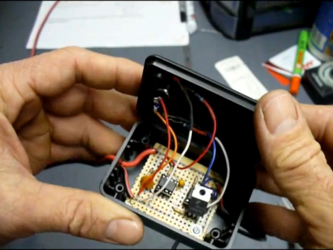
Well... It looks like somebody out there on "The Internets" has finally managed to design and build a cheaper version of the OTC EFI Tester and according to this site and video done by a Dude named "DinoFab"...he has included a parts list, several electronic schematics. bread board information, a seven minute video on how he designed, built and got the damned thing to work. He even has some follow up videos and updates on his design(s) at his home page. And ...most importantly... he even holds out the tantalising possibility that with the removal of one of two small resisters... his little controller might power one EFI indefinitely. The only question is ... How many of these units would be required to satisfy the EFI circuit power draw for more than one injector... say for 4 ...or 6...or even 8 EFIs? I don't know anything about this kind of stuff... but HE DOES and I DO know we have quite a few peeps that follow this thread who also understand all this electronic gibberish. So please...HELP!
Dino.... THIS LOOKS LIKE THE RIGHT DESIGN... NOW....I JUST NEED SIX OF THEM!!!
(...."I don't care if the Cat is White or Black... As long as it catches MICE!".... Deng Xiaoping...)
And this long video is a "Whole New Form of EFI Cleaning Entertainment"... Now you just have to Rinse and Repeat...4...6...or 8 Xs:
Last edited by 60dgrzbelow0; 12-24-2011, 08:07 PM.Comment
-
Okay...
I received a rapid response to my Request For Help from The Man himself at www.dinofab.com, Dino Segovis concerning the use of his EFI triggering device design and the modifications required to duplicate its performance six (6) times...although I suspect making work for eight [8] or more would also be possible, as long as the power supply can hold up to the draw:
Hi Bob. I'm glad my work is of interest to you.
You can take my EFI tester and run multiple injectors with a simple mod repeated for each injector you want to trigger. Just build the circuit as you see it in the attached schematic, then build the highlighted section of the circuit for each injector and connect it to the output of pin 3 on the 555. The MOSFET handles the switching and the load because it's connected directly to the 12 volt supply. The positive output pulse from pin 3 of the 555 chip is what turns on/off the MOSFET.
Let me know how it works out.
Dino
The attached JPEG image shows the areas involved in the needed mod to this design. So...finally.... I can say...."THANK YOU, DINO SEGOVIS AT WWW.DINOFAB.COM FOR YOUR GENEROSITY AND QUICK REPLY TO MY NEED FOR THIS HELP!"Attached FilesLast edited by 60dgrzbelow0; 12-29-2011, 12:02 AM.Comment
-
-
Okay...
As promised, I went back to square one on testing out the new 4thGenFrank Fuel Rail by removing the "unclean" and not-as-yet rebuilt set of GM Multec II 4.2L EFIs and replaced them with a matching set that I put through the ringer of (1) External Cleaning (2) Fuel Basket Replacement with Ultrasonic cleaning (3) EFI Cleaning Fluid pressure cleaning (4) Two Flow Balance Tests that provided me with such ambiguous results that it prompted me to take( yup... We're back to using Bed Frame Parts again!...) one of those angle iron bedstead right angle brackets and mount the old 3rdGenFrank EFI Fluid Cleaning Rail in front of its newborn brother to perform an additional set of Flow Balance tests to try and thrash out the question of whether the sketchy balancing results on the latest version are the results of some other, as yet unidentified phenomena that requires further thinking to solve. I shot four (4) new videos and I note that I had some trouble watching them from the photobucket link due to low bandwidth and I suspect that its simply a problem on my end.
And now for something quite "Fasten" ating:
These links and information probably deserve their own new posting, but since their use in this case followed my normal thinking and problem solving processes for this particular project, I will mention them here. A while back, I posted a link to a Youtube video of a dude making his own special one injector cleaning tool and remembered that at one point he determined the necessary Inside Diameter for the brass fitting he would use to hold the "O"ringed EFI with was drilled out with a 25/64ths drill bit. This latest problem with the GM Vortec Rail has me thinking about going back to investigating the use of brass piping and brass fittings exclusively in a way that a new rail could be constructed WITHOUT all that laborious mixing. matching and brazing of those 3X00 EFI port Tits onto the rail.
CNCGuy, Ben (Sappy) and John (Forced Firebird) probably have all of this information already, but for the rest of us (me too) regular folk... this stuff is really interesting and quite useful. While poking around, I stumbled upon the links below that most of us will appreciate either downloading or linking to for some future referencing. In particular... the one about the Shipbuilder's Outside Mechanic has LOADS of good information, although dated back to 1942 at a time when building ships and hiring qualified new and advanced mechanically inclined people was absolutely necessary to win the world war.That reference material includes information on exactly HOW to use so many measuring tools that we rarely ever properly investigate or know as intimately as true Machinists know them. The other site refers to the folks who brew their own beer and require both sanitary 303 Stainless Steel fittings and hosing, etcetera, along with the various SAE S/S bulkhead double sealing fittings that employ High Temperature Silicone "O" rings which MIGHT just come in handy for use in other automotive applications.
Here are more Naval PDF Training Manuals than you can shake a stick at!
Oh... and here is what can only be described as a clever "Single Vector, Deep Woods 'CNC' Machine" LOL
Attached FilesLast edited by 60dgrzbelow0; 02-07-2012, 11:15 AM.Comment
-
-
The attached cool (actually its HOT! ) and interesting image is from one of the numerous training PDFs available at this site:
More Naval Training Manuals (PDF Format) than you can shake a stick at!
Attached FilesComment
-
-
If you've seen my post, images and videos on “My Neighbor's 900+ Horsepower Toy” the blue early model Chevy Nova II, then your familiar with a man called “Eric” who makes his living as a Diesel Mechanic and, having seen the various generations of “Frank” in action with me at the helm of this device in my driveway, he was prompted to ask for my help after his Dad's 1993 Ford Tempo just died right there in the street in town leaving him stranded from a failed electric fuel pump.
After crawling around to do the dirty work of extracting and replacing that fuel pump in the Tempo, he thought about the poor condition of the old fuel pump and the in-line fuel filter and rightly surmised that after being pounded on and squirting enough fuel through the system for around 200,000 Miles... it might be a good idea to also attend to the four fuel injectors inside that little motor. Of course, I never say no to any of my neighbours when they need my assistance, so I told him I would do my best to clean, recondition, rebuild and bring the gnarled EFIs back to life.
The subject at hand worth mentioning here is that I have to be completely objective about the ability of “The FrankInjector Machine” to do as loyal a job on cleaning other than strictly General Motors Electronic Fuel Injectors. These are not our familiar Rochester Multec I or Multec II style of injectors, but factory OEM Ford EFIs Model# F03E-A2B (probably made by their supply line company: Motocraft). Unlike the all stainless steel, protected and submerged spinnerets of the Multec design, these high impedance injectors have a true pintle in the nose that requires a nylon cap to protect its delicate design. Without that cap, the pintle can either be bent, or broken off without much effort and render the injectors inoperative. The other interesting thing is that cleaning these style injectors for the first time will allow me the chance to tear them apart and memorialise each step of their re-conditioning.
Based on some very happy prior experiences of dealing with “Mr. Injector” for my EFI re-building supplies, I sent him (Mr. Bill Johnson) an email describing my unfamiliarity with these EFIs and he promptly alerted me that he had the right re-build kit to service the EFI Set, As usual, he came through with flying colours by sending me a very generous repair kit that even included four (4) additional red fuel filter baskets to service the Nippon-Denso style of EFIs should their innards turn out to be of that flavour. Using eBay, I dropped $20.00 on this set with free shipping and they arrived here, post-haste today. The weather is bad here today, so I won't be able to get to work on them unless the sun shines again and I can move "Frank" outside for the sake of safety and fire hazard. I'll shoot the proper break-down and re-build still shots and two videos of the pressure cleaning and Flow Balance Test by and by and soon we'll have Eric's Dad's car running like a top. The video link below shows a training session in which these particular injectors are being broken down for repair by Bill "Mr. Injector" himself:
Attached FilesLast edited by 60dgrzbelow0; 02-08-2012, 03:12 AM.Comment
-
Comment