 Tweet
Tweet
no, just thought it might be an easy way for those of us not so skilled with software, but are capable with hardware...
-
Robert... when Rick mentioned "DUNE" and you suggested using "SOUND TO CONTROL"... I just could not help but think of using THIS device.... Now THAT thing will modulate your EFIs to DEATH!Originally posted by robertisaar View Post Attached Files
Comment
-
-
Okay Folks... (Looks like somebody broke us past 10,000 + hits on this topic!)
Hold on to your Hats... and your Short and Curlies...
Here is another engineering-style free thinker (...calls himself "marks" on YouTube) who has not only built his own fully functioning Fuel Injection Cleaning Machine and solved ALL the problems that prompted my initial thread question... but his device also makes "The FrankInjector Machine" look like Baby Shit! LOL.... I wish to Hell I could dope out what sort of mechanism he employs for his VFiFC component (Variable Fuel Injector Firing Component)...that thing works GREAT!!!!
Take a look at these YouTube Videos and you'll see what I mean!
I quote here what he has listed in the comments section on YouTube about this EFI controller...
"The links are on the "ford escort injector cleaner" video there are link to a blog page that shows where I got the idea for the rpm circuit, The 555 just gives a saw tooth output wave and the comparator gives the p/w modulation control. Also for the comment on the bottom I use 12 volts for the injectors and 5 volts for control, See referred links above."
Here is the link to the blog that has the actual nested link to the "How To Build" the thing that is what I have been waiting for now for so long...

Okay... Hopefully...after seeing some of these circuitry images at this link, some of our own folks who know and understand these things can figure out exactly what he used to make the controller and explain the parts and pieces of it... and then... show the rest of us how to build our own version... Yes?.....
MY GOD...THE MAN HAS EVEN GOT A HAND-DRAWN SCHEMATIC FOR HIS CONTROLLER-DRIVER BOARD THERE!
(Rick... I hope this does not dissuade you from making your own version with your "RIXinjector Machine)
Considering that "marks" conceived and built his own machine several years ago... (and deserves "High Marks" for it, too)...here is my observation concerning the originality of my own thinking...Originally posted by Superdave View Post
"There is NOTHING New Under the Sun..." William Shakespeare - Sonnet 59Attached FilesLast edited by 60dgrzbelow0; 07-14-2010, 08:19 AM.Comment
-
-
I waded through the blog where "MARKS" goes by the name "R NARKS" and culled out another circuitry diagram that was apparently th nexus of his CONTROLLER-DRIVER BOARD idea for his EFI Cleaner Machine. Once again... all of these electronic elements are Greek to me... but perhaps the more astute among us can take up this portion and run with it... Like Rick is doing, also... Here is the link to the project:
Comment
-
I will have to read this thread for more details on what your trying to get the circuit to do, but thay circuit is very easy to make, I'm pretty sure radioshack stocks 555 ics, but I'm not sure. PM me if you need electronics help.Comment
-
radioshack does indeed have 555s.
i grab electronics stuff in quantities that would be bad for radioshack though.....
good company, if you can wait on shipping.Comment
-
Welcome to the thread, HOYS... and thanks for the offer of help. This Epic Post is peppered throughout with many suggestions on how the EFI controller might be made...but no plans have solidified to date. The problem which I have been facing all along since posing the "Q" on this subject is that I may know my way around a workbench in many odd and sundry ways... but when it comes to anything electronic that involves anything more than plugging things in... I wouldn't know a Bull's Ass ...from a Bass Fiddle... So the numbers "555" do not register a solution in my electronically dyslexic lexicon. The help I need is for someone...anyone with enough understanding of these things to just build a controller similar to the one shown in the recent videos done by "MARKS" and then take enough close up images of it that somebody like me can get the parts you might suggest from "The Shack" or as Robert suggested...another vendor...and plug the necessary parts into a breadboard...solder them in well and truly...hook it up to "The FrankInjector Machine" and just turn it on... and watch the magic happen...Originally posted by HOYS View Post Last edited by 60dgrzbelow0; 07-12-2010, 07:05 PM.
Comment
-
A few things before my battery dies:
555 is a very common type of IC. A good read:
Yes, the 555 has its own wikipedia page. Essentially a 555 IC acts as a variable timer to control a circuit. In the videos you posted of the epic injector cleaner, it functions as the "RPM" knob. It regulates the power going to the solenoids in the fuel injectors depending on what you turn the dial to. It sends the little blips of energy faster or slower depending on how you turn the knob.
What other questions? I'd be willing to spend a few bucks and solder this together for you if you needed it.Comment
-
"Monostable mode: in this mode, the 555 functions as a "one-shot". Applications include timers, missing pulse detection, bouncefree switches, touch switches, frequency divider, capacitance measurement, pulse-width modulation (PWM) etc
Astable - free running mode: the 555 can operate as an oscillator. Uses include LED and lamp flashers, pulse generation, logic clocks, tone generation, security alarms, pulse position modulation, etc."
seems it can have multiple uses in auto environments.....Comment
-
Shouldn't have to go that deep into the IC...just have to make the circuit...if you must know it would be running in astable mode as an oscillator...Originally posted by robertisaar View PostComment
-
Okay...so far...so good on the basic capabilities of the "555" Chip as a switching tool... but in looking at "MARKS" "MARKSInjector"... it appears that he has three major segments to his controller hardware:
(1) A Power Supply that looks like it comes out of something related to aviation/avionics.
(2) The breadboard that has the variability adjuster on it.
(3) Another breadboard that fires the EFIs.
I might be wrong here...but when watching the video(s) of the machine in action... it appears that he is firing all four Ford Escort EFIs in an oscillating pattern, rather than firing all four EFIs at once... either very rapidly or slowly as a group. If that is the case... wouldn't it place less demands on the need for a big and bulky power supply since only one injector at a time is receiving the power surges and amperage demands for the varied durations?
I can almost guarantee that for this phase of the project... I'm useless in trying to climb whatever learning curve is necessary, then grab-bag the required parts and pieces to build something workable that can be plugged into an injector harness. But if somebody else can build one and show me exactly what to do... then I would be able to "Monkey-See Monkey Do" one together on my own.Last edited by 60dgrzbelow0; 07-13-2010, 12:32 PM.Comment
-
This is exactly what I need for a wet flow bench and injector tester.Ben
60DegreeV6.com
WOT-Tech.comComment
-
The power supply should be easy, rig a cheap computer power supply to turn on when you want, and take a 12v line into your circuit, the first controller we have discussed and should be fine. I'm trying to figure out how he drives the injectors from the other board, ill have to do more reading. I believe the injectors fire all at once.Originally posted by 60dgrzbelow0 View PostComment
-
Ben...Originally posted by SappySE107 View Post
When I stumbled on to this site looking for the electronic "How-To" for this project... it occurred to me that you...and John (Forced Firebird) as well as CNCGuy might want to look this place over.... assuming of course that all of you are not already members there... It looks like a very interesting place for a machinist to enjoy.
Comment
-
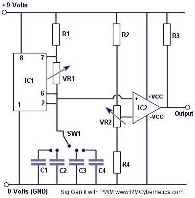
The 555 and all its imitations have been around forever. Circuit cookbooks and the Internet are littered with example schematics that you could use. It's an analog IC that relies on an RC time constant for timing, so it's not very accurate but it would get the job done for simple cleaning. The 555 datasheet from many manufacturers has example circuits for creating saw, triangle, and square waves as well as the equations to calculate duty cycle and frequency. It's a piece of cake to make a square wave generator with variable frequency and duty cycle and use that as input to the power electronics that drive the injectors. You can not drive the injectors directly from the 555, though.
The guy linked previously is using an LMD18400 quad high-side driver to drive the injectors. It's a bit expensive and hard to source. Digikey currently has some for $12.25. It drives 4 outputs. You could make the same thing for a lot cheaper with MOSFETs (minus the digital feedback which he isn't using anyway).
He is surely driving them simultaneously and not in any kind of sequence since his circuit has only 1 output. Google "555 pwm motor speed controller" and there are several circuits you could use to start with. Find a circuit with both a transistor output and a free-wheeling diode (reverse-biased diode across the motor/injector/relay/etc.). It's more useful to vary frequency than duty cycle. A fixed duty cycle of 50% would work great. Fuel delivery isn't metered by duty-cycle, it's metered by pulse-width. Duty cycle calculations are useful for determining if your injectors are undersized for a particular application.
What I'm building is a lot more precise (and repeatable) and drives 8 injectors. My goal is not only to see if the fluid levels are even but to make flow measurements in order to characterize injectors before/after and under different simulated conditions.
I just got back from a short trip and now I'm back to juggling my projects. I've been waiting for my graduated cylinders to arrive so I can measure their height and finish building my machine. The cheapest ones I found are Here and Here I also just received some injector connectors from This Guy for about $2 each. They have rubber seals and a metal spring clip. The quality is nothing to rave about but they were the cheapest I could find and I have no complaints.Comment


Comment