Announcement
Collapse
No announcement yet.
roller lifters with 2.8
Collapse
X
-
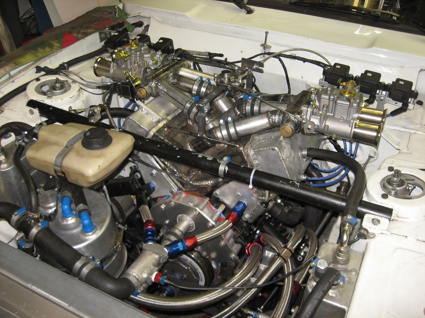
I got the engine running today.
Everything seems to be allright.
No leaks, no smoke ,sounds good.
Next step is dyno,maybe tomorrow I visit the dyno place and ask for a appointment in a 2 weeks time or so.
Edit: dyno time thursday 28. november 2013
 Last edited by veekuusi; 11-15-2013, 11:18 AM.
Leave a comment:
-
Man, your fabrication skills, and patience, and tenacity are amazing! Thanks for sharing this here. Can't wait to see more.
Sincerely,
David
Leave a comment:
-
If that was a lot more refined, I'm betting that the design u established would be a hit in the carb ccommunity.
Leave a comment:
-
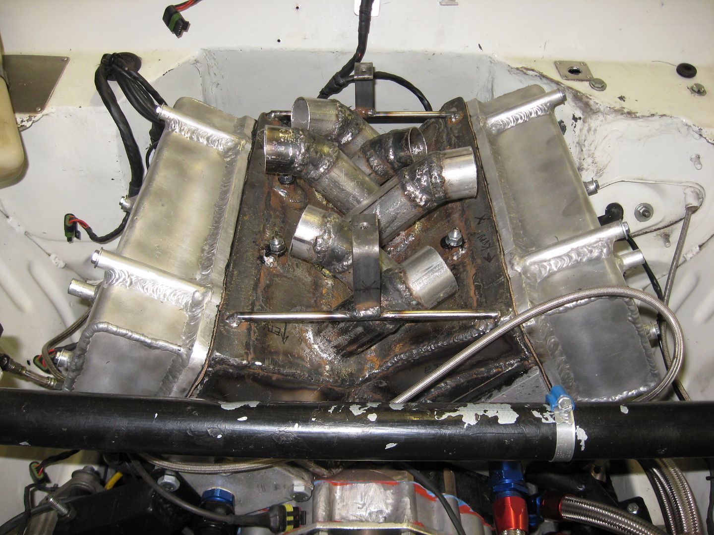
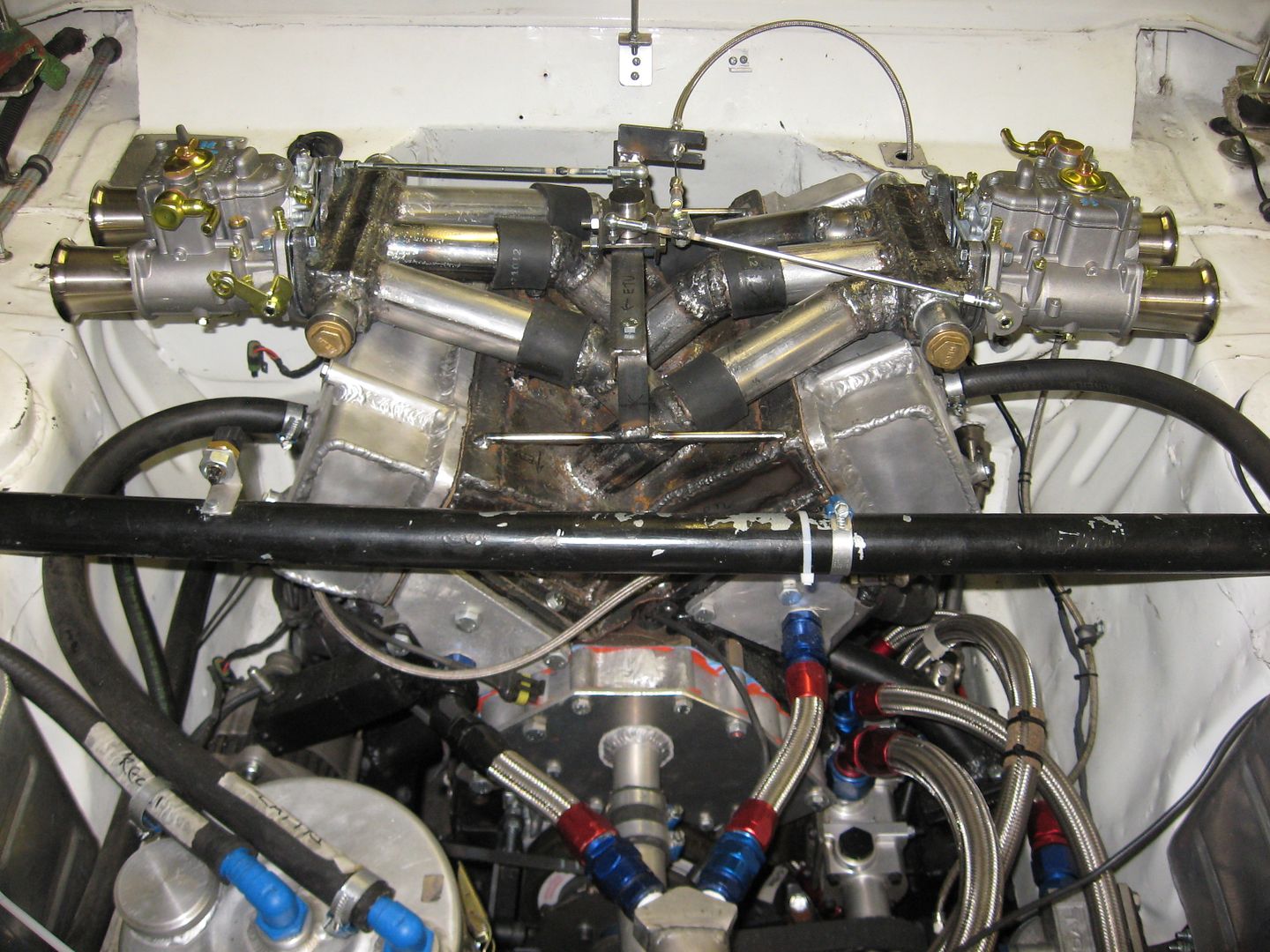
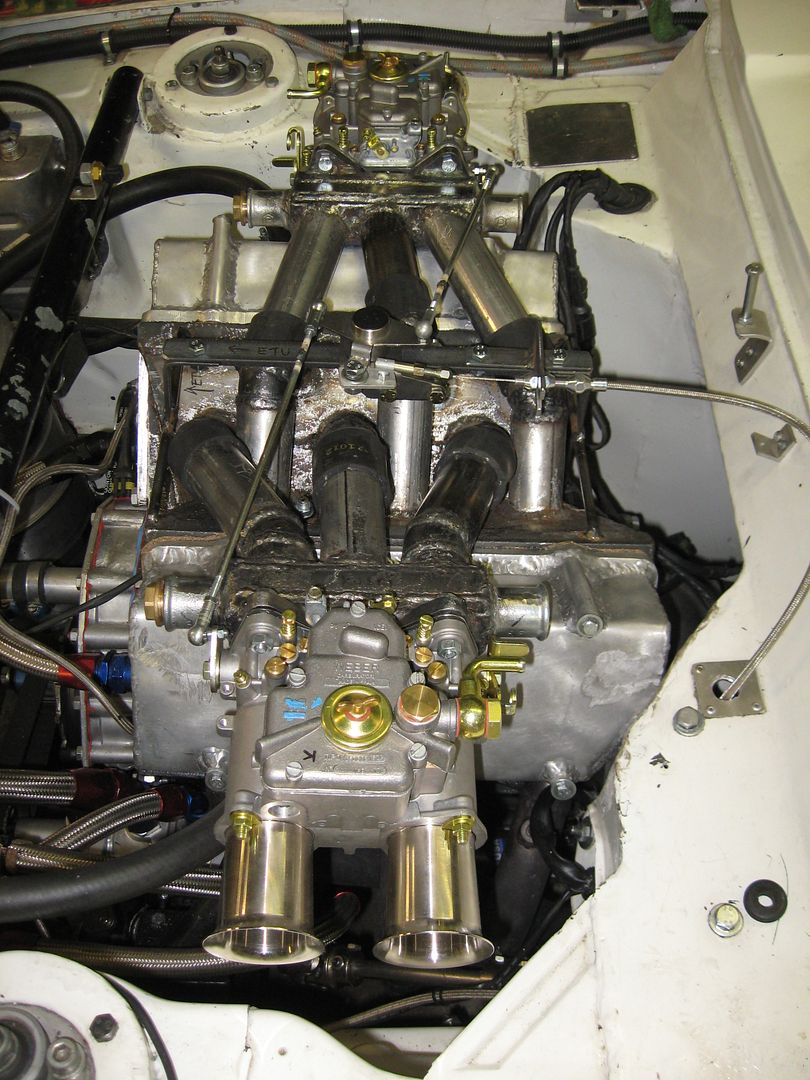
This is what it looks like in my garage today.
I had to cut the intake runners because of the valve covers.
There are rubber connections in each runner (yes , I know, the clamps are still missing, do not worry).
Now it is possible to install the covers without pulling the intake.
Otherwise it would have been required to pull the intake allways lets say to check the valve clearance.
I am pretty sure the "LIM" is now eventually ready.
But it is now easier to make adjustment to the "UIM" .
I am not forced to pull the whole intake but only the UIM.
Lets say to make the plenum bigger etc....
I did not yet bother painting the intake.
It is possible to see leaks and if the intake needs modifying ( read: welding) ,
it is easier this way.
 Last edited by veekuusi; 11-02-2013, 11:02 AM.
Leave a comment:
-
I am using mig and tig welding (of course dc tig with iron).Originally posted by 1988GTU View PostI am curious how you are testing for leaks in the pipes after welding?
You using arc Mig welding?
It is pretty easy to have pores,fractures etc with mig.
Tig is "bullet proof" when it comes to leaks.
That is why almost every joint that has been mig welded , has been "melted" afterwards with tig.
It is so much "easier" and faster to mig weld, and in this case it is not possible to reach every place
with a tig torch.
In the 2 earlier intakes , I tested the leaks simply with soap water.
You have to block the runners, which is not that simple.
If there is a hole in the runner which largeness is like a pin, I dont
think that is a very big problem.
Leave a comment:
-
I am curious how you are testing for leaks in the pipes after welding?
You using arc Mig welding?
Leave a comment:
-
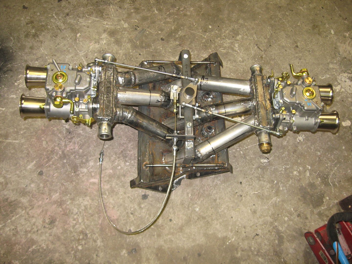
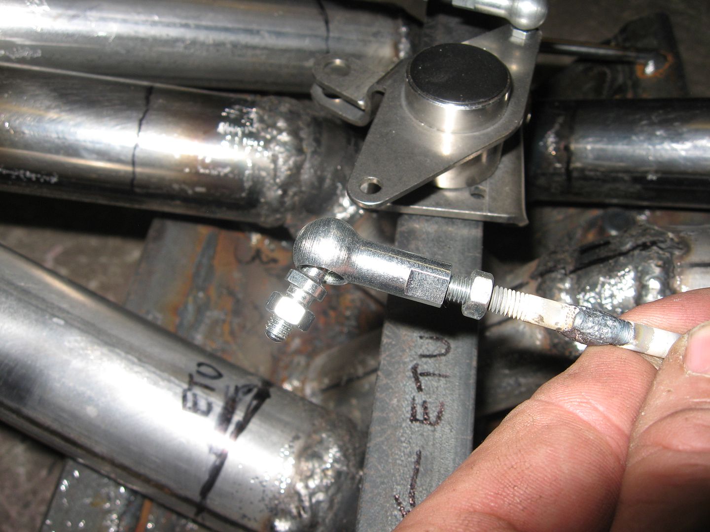
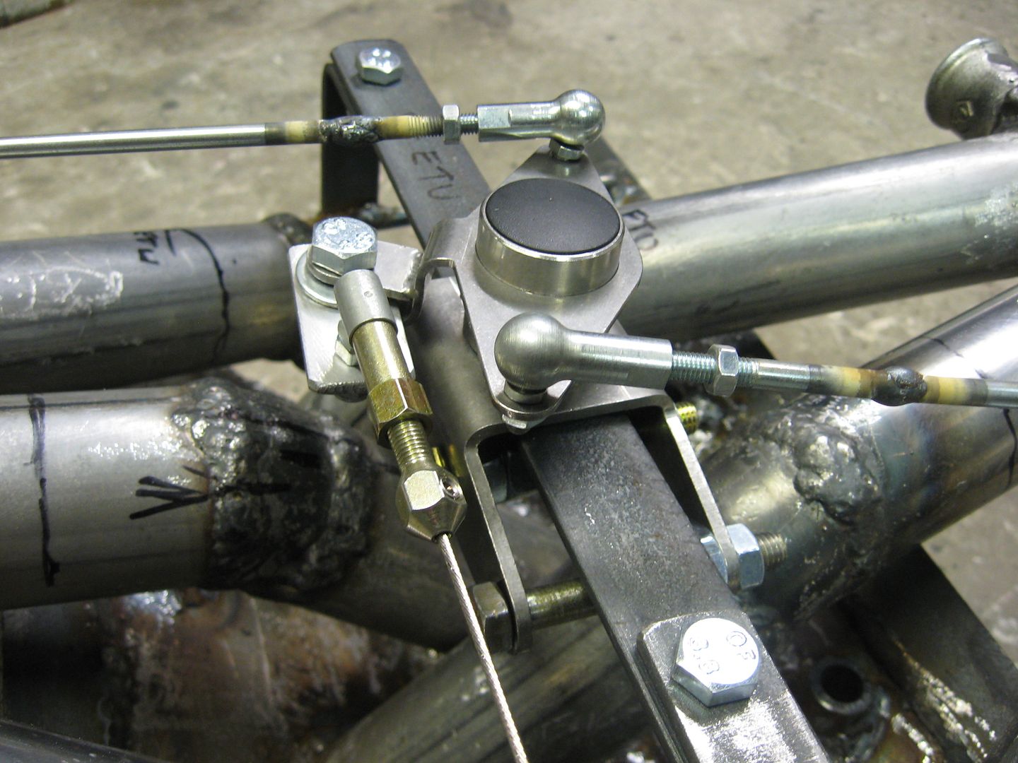
The throttle linkages are pretty much done.
I used aftermarket aircooled VW boxer engine (Beetle) linkage.
I had to modify them a little, but no big deal.
TPS sensor is next to do.
Leave a comment:
-
 Guest repliedAre you trying to add plenum volume through the use of garden hose?
That will act more as a Helmholtz resonator than adding plenum volume, which may or may not have benefits.
As suggested a balance tube might help as well, but over that distance I think it will act more like an air spring, or resonator (different than the Helmholtz resonator). It's all worth a try, but I think the application is different than your theory.
Leave a comment:
-
might also play with a balance pipe to see how that affects power.
Leave a comment:
-
I would say there are 45 degree angles in my plenum area.Originally posted by 23TrackroadsterV6 View PostI have admired your handy work and ingenuity for quite some time. I have serious doubts about how well this manifold will flow and have "even" fuel distribution. Looks like lots of 90 degree angles in your plenum area. If port fuel injected, not so much of a problem, but with carbs. I think it will lead to some cylinders running richer and or leaner than others. Just my opinion.
Nobody knows yet how this intake is going to work.
But your comments are welcome,this is something a few people has tried ,
and fewer has writen the results to the internet.
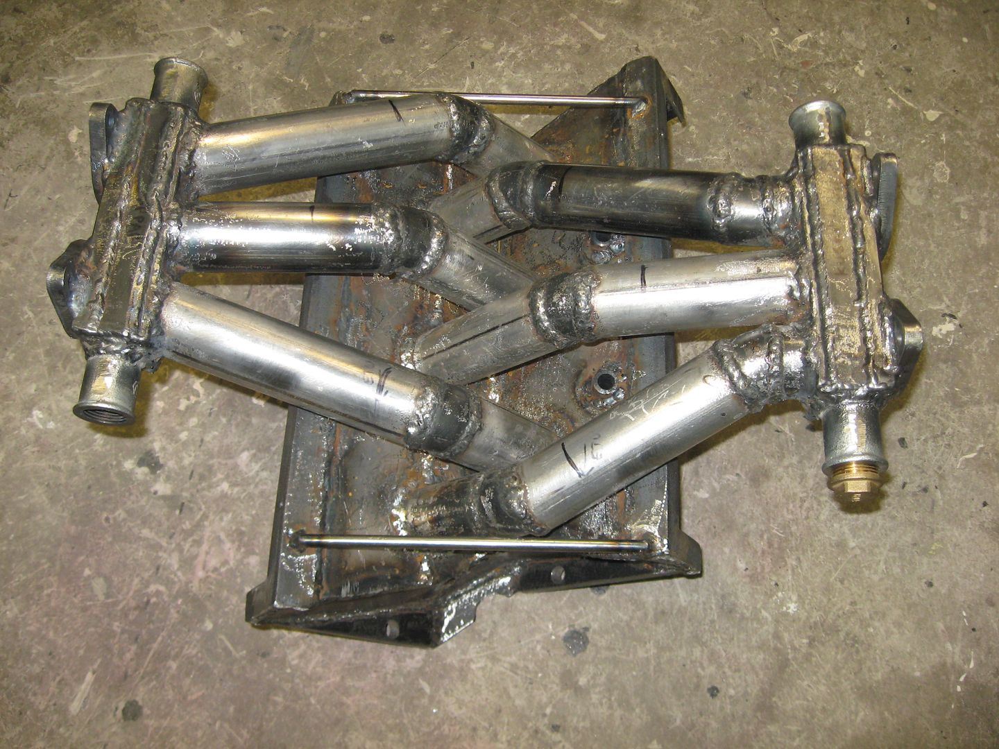
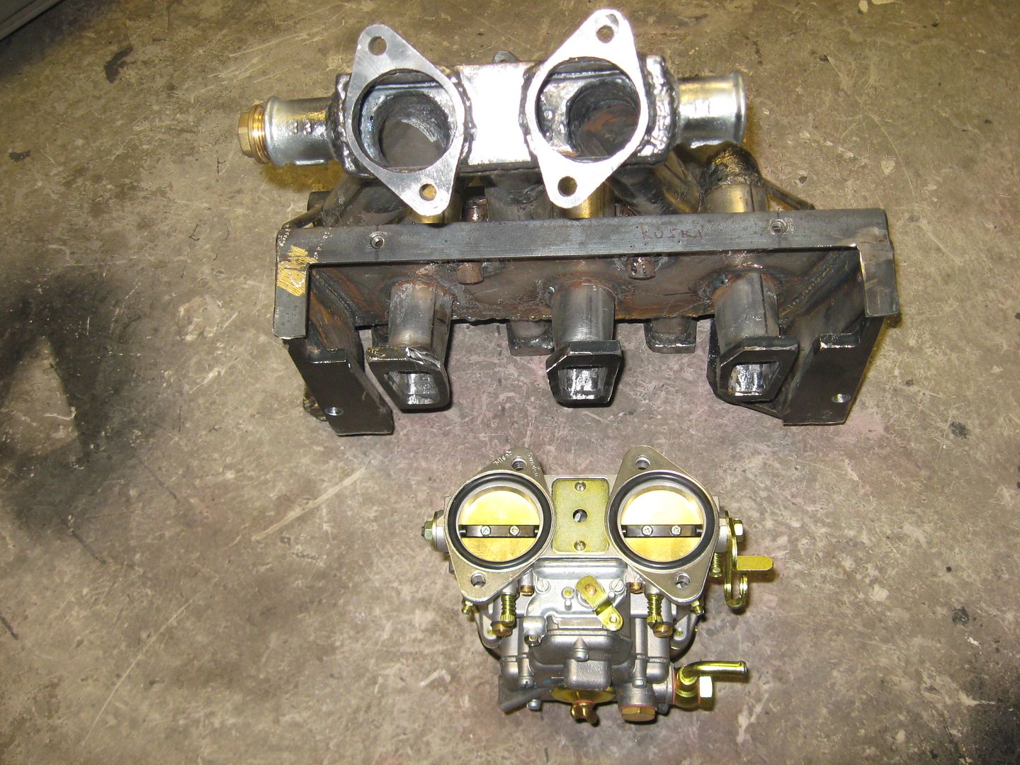
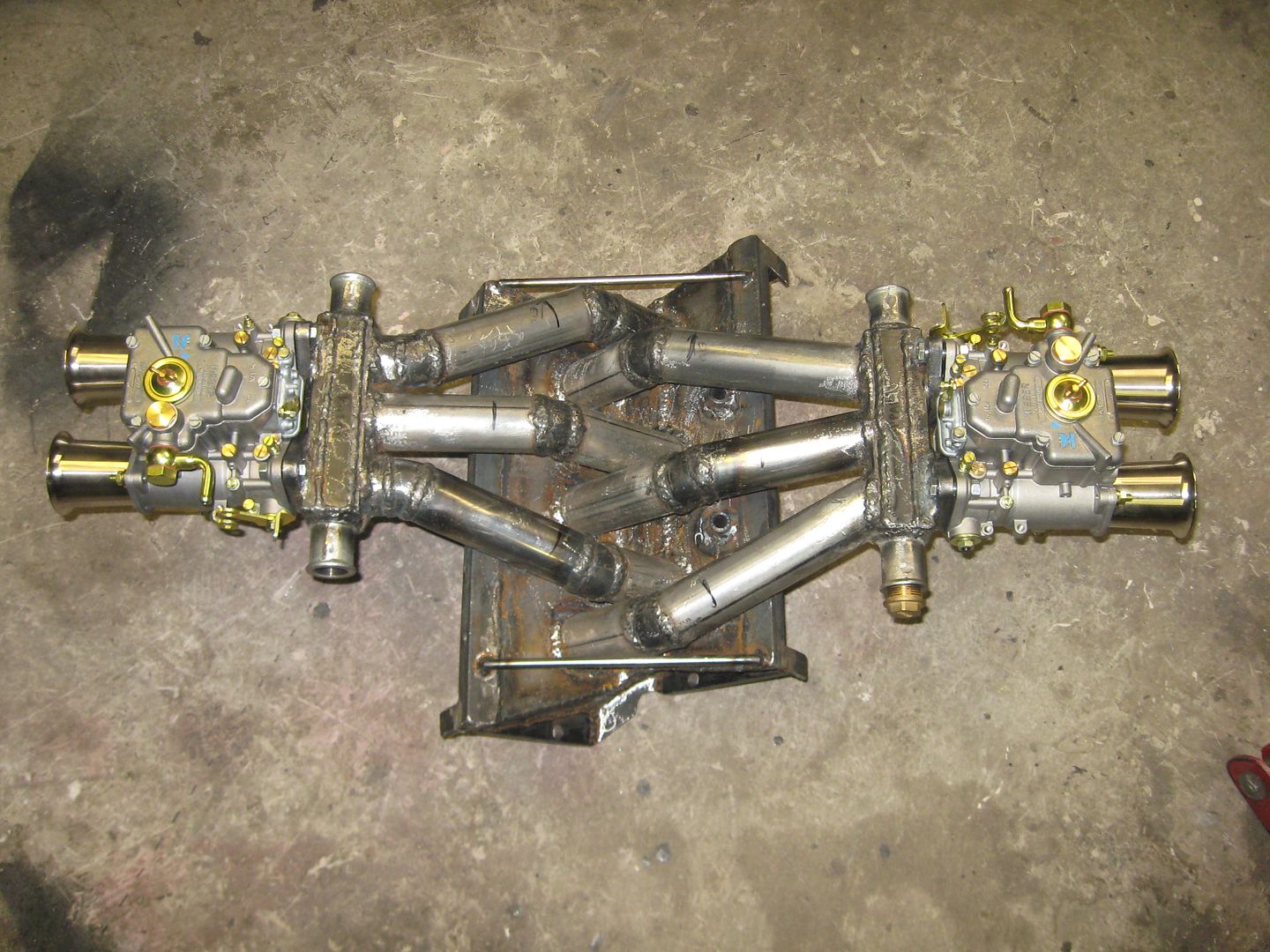
Following picture is taken some 45 degree angle .
So the middle one cylinders has to suck air from both throats in 45 degree angle.
There is a possibility to monitor 2 exhaust temperatures at a time in the dyno.
It is going to be very important data to analyse.
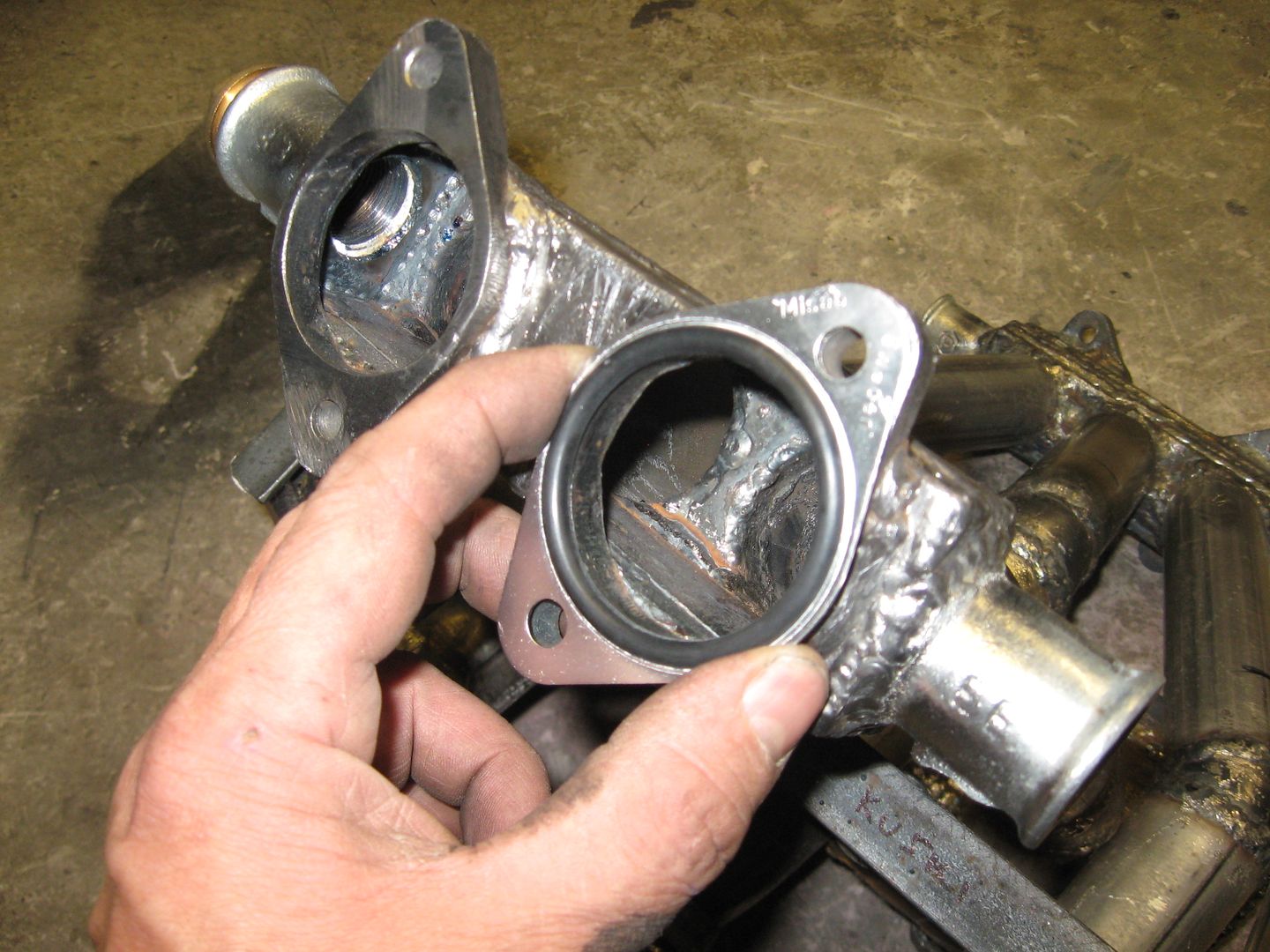
I welded 3/4 " pipe connections to every end of the plenum.
So in the dyno session I can experiment different air connections.
I mean, if the plenum is now too small, the cylinders can suck more air through them .
Or I blug them if they are not needed.
I have to buy some 10 feet "garden hose" for the dyno.
Leave a comment:
-
Last I checked he does have EGT ports so it might be a wise idea to bust out the sensors and keep any eye on the two center cylinders vs the outer's.
Leave a comment:
-
I have admired your handy work and ingenuity for quite some time. I have serious doubts about how well this manifold will flow and have "even" fuel distribution. Looks like lots of 90 degree angles in your plenum area. If port fuel injected, not so much of a problem, but with carbs. I think it will lead to some cylinders running richer and or leaner than others. Just my opinion.
Leave a comment:
-
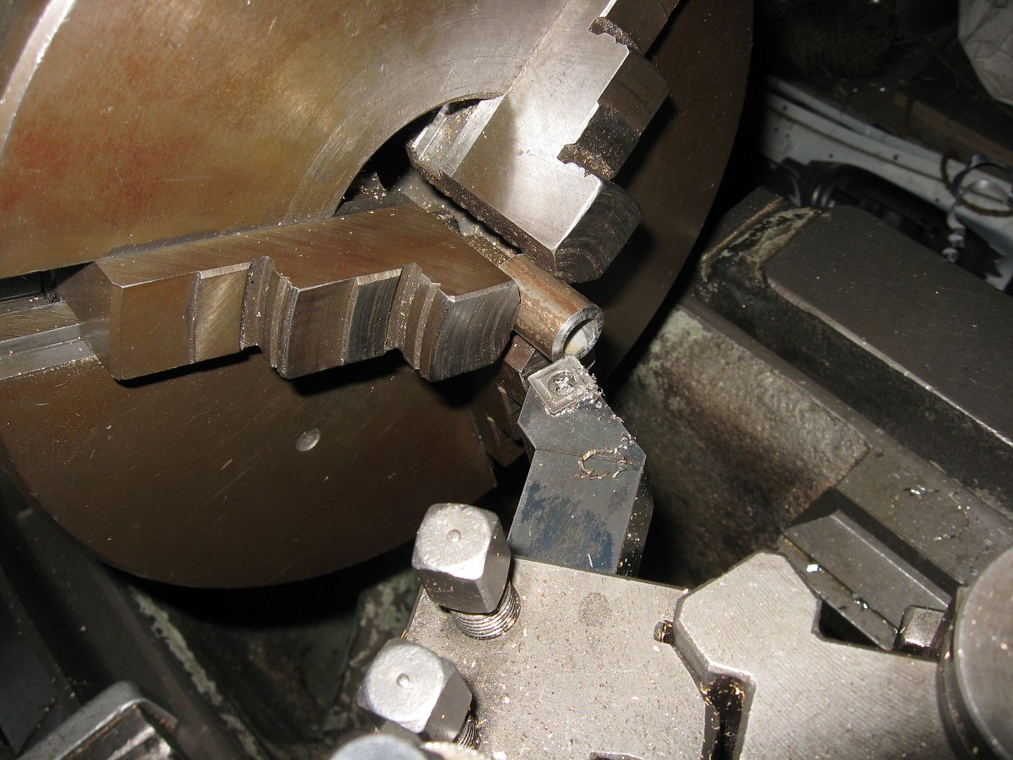
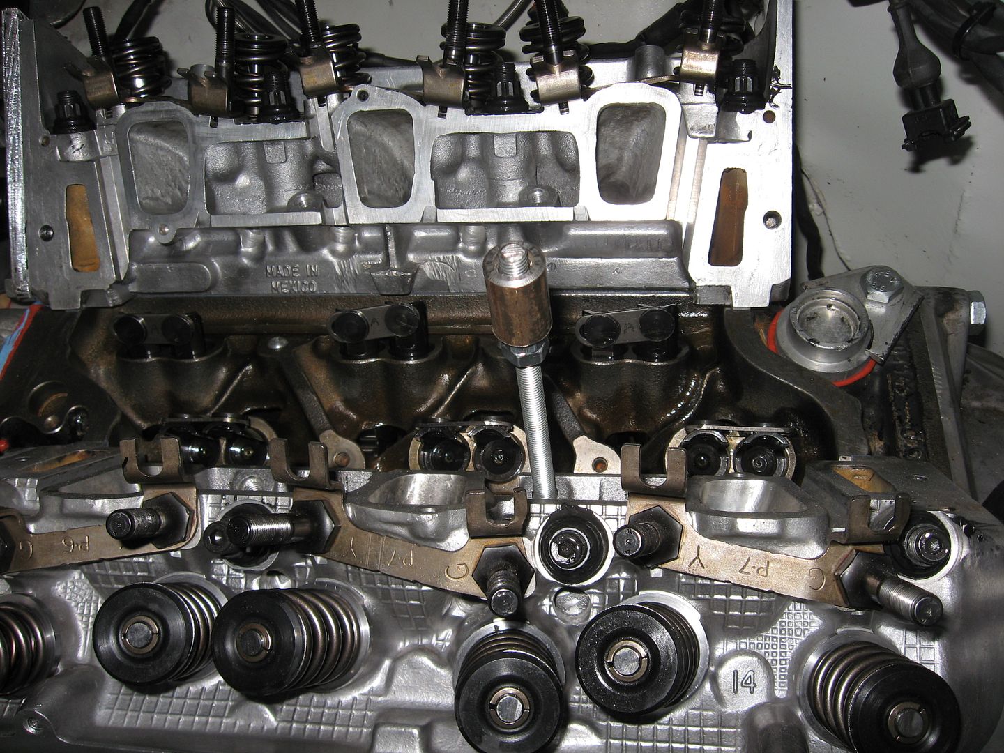
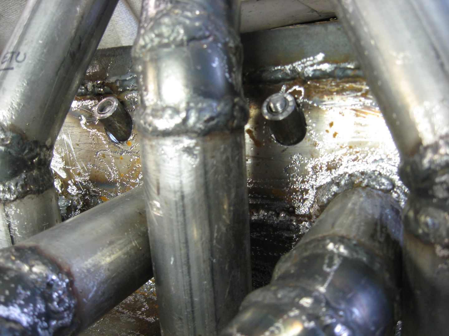
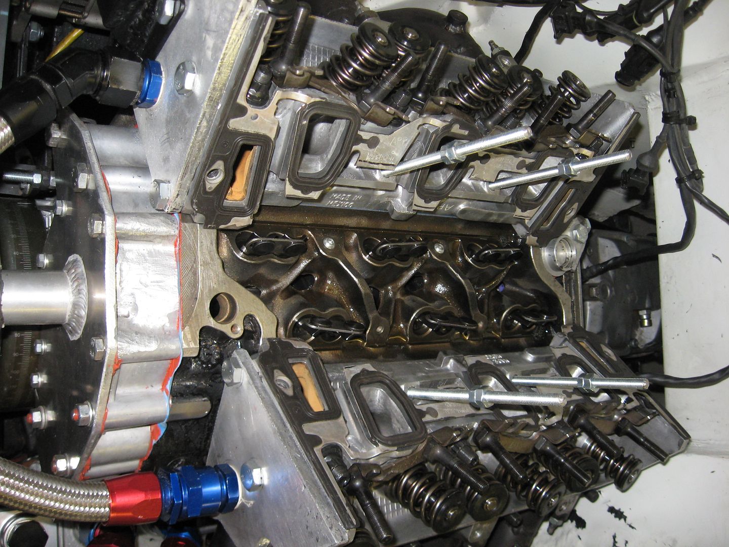
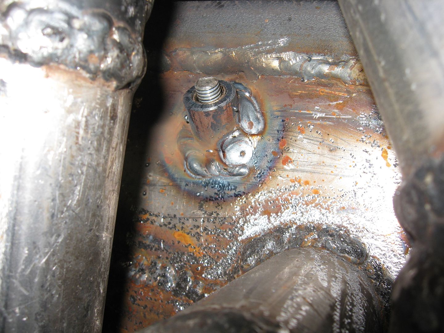
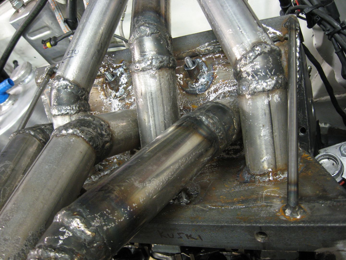
A picture is worth a thousand words.
Modifing the intake for the 4 middle one bolts or studs.
Leave a comment:

Leave a comment: